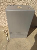
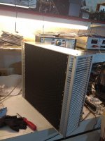
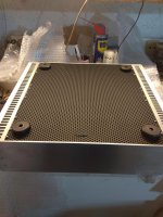
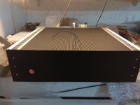
Just finishing things up with the amp. Only thing left is install the top 1/8" thick aluminum cover, and cut out a 50mm circle in the rear center of the chassis for a 50x15mm Sunon exhaust fan that will run at 5v instead of the normal 12v. Its completely silent at that voltage and moves enough air to keep everything cool. You can't see from these photos but the bottom plate has the front 1/3 perforated for air to enter the case. All the wiring was done using 18ga solid core becuase thats what i had on hand. The RCA to Aux wires probably should have been much thinner, so i may re-do them in 24ga solid.
I'm fairly pleased with the end result though there are definitely some things i'd do differently next time. But since this was my first amp chassis, i didn't have the highest expectations.
I'm fairly pleased with the end result though there are definitely some things i'd do differently next time. But since this was my first amp chassis, i didn't have the highest expectations.
Attachments
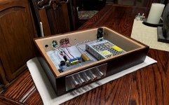


My approach for a preamp enclosure. Made from scrap alum sheet and tinted acryl.
Details on the forum :
RS-PA3 : A Fully Reed Switched PreAmp
or:
RS-PA3 Reed-Switched Pre-Amplifier
Details on the forum :
RS-PA3 : A Fully Reed Switched PreAmp
or:
RS-PA3 Reed-Switched Pre-Amplifier
Attachments


Small cosmetic triks,more safe for your hands too. 😉
I've been thinking of putting a round-over on mine. Too Sharp!
Hello!
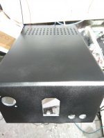
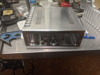
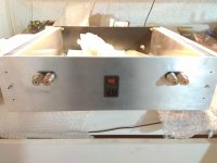
I'm building 6 monoblocks right now, and after thinking about what boxes to make, I decided on the following option.
From the sheet metal, I built the internal skeleton of the amplifiers, making sure that the power supply was separated / shielded / from the circuit boards.
Since the monoblocks will be in bridge mode, there will be 1 radiator board on each side and the power supply in the middle.


I know it looks pretty ugly, but it's the internal skeleton of the amplifiers, the supporting structure, and you won't see any of it in the final version.
When completed, there will be facade panels installed around the skeleton.
The topic is very interesting and contributes to the exchange of experience.
Greetings!
Not at all. Nicely thought out.
Last edited:
I think there's some drawback with these profiles at the edges, as they might hinder convection somewhat. But it really looks very nice!
Best regards!
Best regards!
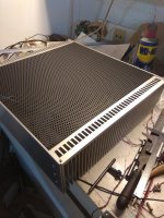
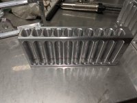
The Simpelstark amp runs fairly moderate rail voltages so it doesn't produce a lot of heat. Convection still works with the ends covered but it isn't quite as effective.
I've been experimenting with heat sink designs similar to the profile Jeff Rowland has made famous. They actually cool much better than one would expect. Chatter in the cutter is a huge problem though.
I've been experimenting with heat sink designs similar to the profile Jeff Rowland has made famous. They actually cool much better than one would expect. Chatter in the cutter is a huge problem though.
Attachments
The Simpelstark amp runs fairly moderate rail voltages so it doesn't produce a lot of heat. Convection still works with the ends covered but it isn't quite as effective.
I've been experimenting with heat sink designs similar to the profile Jeff Rowland has made famous. They actually cool much better than one would expect. Chatter in the cutter is a huge problem though.
Really like a Jewel!
Looks like very expensive too. 🙁
Always is an option to remove those if i will see a problem but i like the look.😎
You can save your hands in the end.😀
Last edited:
I keep seeing the term "scrap aluminum" being tossed around a lot, but when i look at pics i see beautiful blemish-free heatsinks, bars, plates etc.... all heavy gauge. It's almost as if "scrap" has a different meaning in my ancestral home country, perhaps something akin to "lifted from a local metal fabrication business". 😉 😀
Good effort on your amp chassis, Thimios It looks very sleek.I think there's some drawback with these profiles at the edges, as they might hinder convection somewhat. But it really looks very nice!
Best regards!
I've built similar chassis for Class A amps, where heat dissipation is definitely an important consideration. The most elegant way is to build an all-aluminum chassis and have adequate heatsink to dissipate output device heat quickly. The highest thermal area will be adjacent to the device interface. A massive pleated heat sink may have 50 c difference from the device interface to the edges of the heatsink, This heat dispersion indicates that the heatsink should have enough mass and pleating to dissipate device thermals adequately at the interface area.
I found one interesting heat dispersion design that replaced perforations or cutouts and screens in the top plate of the chassis. I raised the top plate 1/4" from the chassis. This allows a continuous top vent space of of over 50 sq in. for most large amp chassis. No dust, beer, wine, or candle wax can intrude into the chassis. If your listening space is infested with cockroaches, you may wish to screen the vent, they get into everything that has a raised temp in the dwelling. No roaches here because we have Winter, High temp tomorrow is forecast for 2F.
Good luck on your builds. You have talent there

I agree with "...different meanings...", but I used real aluminum scrap for the case (post #103)I keep seeing the term "scrap aluminum" being tossed around a lot, ....... It's almost as if "scrap" has a different meaning in my ancestral home country....
similar to the attached picture.
😀
Attachments
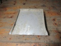
I agree with "...different meanings...", but I used real aluminum scrap for the case (post #103)
similar to the attached picture.
😀
Oh i know. I just wanted to mess with my fellow Greeks from across the pond.
Looking good, thimios.
I don't think I'd have the wires coming out the top like that, though....

I don't think I'd have the wires coming out the top like that, though....
- Home
- Amplifiers
- Solid State
- Building your own amplifier enclosure