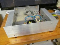
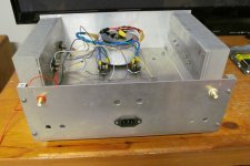
Throwing out ideas , here is the first case I made for Power Amp .
AnTek used to sell heat sink material - I don't think they do any more .
The face plate is just a piece of 0.25 x 5 " piece of flat bar 6061 Aluminum .
This can be cross cut using a table saw , a good cross cut guide , and a carbide blade .
Note that if you are going to cut any material , there should always be at least 2 teeth in contact
with the material being cut .
In hind sight , I should have built the case with the heat sinks at the back
in order to shorten the length of the power supply , speaker and RCA wiring .
.
Attachments

So here is a basic drill and tap chart . If different sizes are needed , here is a more complete chart
https://www.engineersedge.com/thread_strength/internal_screw_threads_chart.htm
4 - 40 - major diameter ( outside of the threads ) = 0.109 " ( measured )
............ minor diameter ( inside of the threads ) = 0.085" to 0.094 "
.............to tap use a No. 43 drill bit , however , a 3 /32 " = 0.094 " drill bit works OK .
6 - 32 - major diameter = 0.134 " ( measured )
............ minor diameter = 0.114 "
............ to tap use a 3 mm drill bit = 0.118 "
8 - 32 - major diameter = 0.163 " ( measured )
........... minor diameter = 0.139 "
........... to tap use a 9/64 " drill bit = 0.141 "
Synthetic motor oil works fine as a cutting fluid .
If you don't have one , Lee Valley tools sells an imperial dial caliper for a very reasonable price .
https://www.leevalley.com/en-ca/sho.../calipers/32609-stainless-steel-dial-calipers
Recommend an imperial one with a dial - not a metric , digital read out , or vernier .
With the hardened stainless steal you can also scribe aluminum with it .
Made in USA Starett will be more expensive , but they make quality products
https://www.grainger.ca/en/product/...5MWlrofAxQC5c_G7lYRoCQE0QAvD_BwE&gclsrc=aw.ds
.
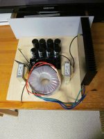
So I'm in the process of making my second power amp case .
Going to use a piece of 15mm thick Baltic birch plywood for the base .
For the face plate , I've just ordered a piece of 0.25 x 6 x 19 " flat bar 6061 aluminum .
The heat sinks are made by Multicomp
MP008442 is rated at 0.42oC / Watt
MP008443 is rated at 0.36oC / Watt
There will be heat sinks on both sides .
Going to use 1.5 x 1.5 " L aluminum , with a 0.125 " wall thickness , as L brackets , to hold up the heat sinks .
For the back plate , was thinking of using a 3/16" thick piece of polycarbonate . *
If anyone has some suggestions here , please jump in .
I'm over thinking this , so I'm a bit stuck .
.
.
* Note : I've heard of 2 people who had accidents cutting polycarbonate on a table saw .
I don't know the details , but make sure if cutting it , it never has the opportunity to bounce .
Maybe the person was foolishly using the ripping fence for a cross cut .
The throat or yoke insert on the table saw , must be flush with the bed of the table saw .
.
Attachments
Last edited:
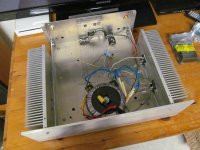
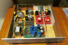
Re post #121...cracking job old chap, it looks very sturdy. Note that you twisted the tfmr leads, nice. Are you going to put a thermistor on the OP of the IEC mains in? I'd put fuses before the bridge rectifiers, a little fuse board might be in order. What are the devices on the HS? dual mosfets, IGBT's or...?
Andy.
Andy.
Andy , Thanks for your support . I was going to separate Hydro Earth and Analog Ground as shown in figure 5 in this article by Rod Elliot
https://sound-au.com/earthing.htm
Going to move the power switch to the front . As I was sternly told on this website , Both the hot and neutral should be switched .
To prevent arching of the switch contacts , connect a cap across the 2 hot terminals of the switch.
Please check this , but as I recall it must be an X rated cap , and I think the value is 0.01 uF ... again check this .
For an EMI filter , I highly recommend building a Fo Felix .
I'll be using a Bourns 8120-RC for the common mode choke .
However , the windings can move a bit so it may need potting .
https://www.mouser.ca/datasheet/2/54/8100_series-777217.pdf
The devices are IXYS IXFN180n10 switching MOSFET 's .
The back of these devices are floating .
As such , there is no issue with the L and R heat sinks being in electrical contact .
Nelson Pass probably used different MOSFET's in his XA25 power amp .
Here are the details of the Amp I've tested ... but I'm now caught up with renovations and others projects .
Listening to this Amp with my simple test speakers - B&W 110's - the the timbre of a piano is fabulous .
The Amp has a source follower output stage .
The transformer shown is a 300 VA made by AnTek with dual 18 Vac and 18 Vac secondaries .
However , if the bias set to 1.2 Amps - For both a L and R channel , 300 VA is right on the border of being too small .
I'm told its best to go with dual 300 VA transformers .
.
https://sound-au.com/earthing.htm
Going to move the power switch to the front . As I was sternly told on this website , Both the hot and neutral should be switched .
To prevent arching of the switch contacts , connect a cap across the 2 hot terminals of the switch.
Please check this , but as I recall it must be an X rated cap , and I think the value is 0.01 uF ... again check this .
For an EMI filter , I highly recommend building a Fo Felix .
I'll be using a Bourns 8120-RC for the common mode choke .
However , the windings can move a bit so it may need potting .
https://www.mouser.ca/datasheet/2/54/8100_series-777217.pdf
The devices are IXYS IXFN180n10 switching MOSFET 's .
The back of these devices are floating .
As such , there is no issue with the L and R heat sinks being in electrical contact .
Nelson Pass probably used different MOSFET's in his XA25 power amp .
Here are the details of the Amp I've tested ... but I'm now caught up with renovations and others projects .
Theme and Variations on a BA-3 driver stage and BA-1 follower output stage
Before soldering this , thought it might be good idea to run it by the experts .
For the voltage gain driver stage , I have some
The Idss ~ 7.0 mA for the jFET's .
Is matching of the lateral MOSFET's required ?
With the jFET's biased at around 4.2 mA to 4.7 mA is this enough current to be able to effectively drive
the lateral MOSFET's . Is there a cook book equation people use for this ?
The lateral...
Before soldering this , thought it might be good idea to run it by the experts .
For the voltage gain driver stage , I have some
- 2sk246 BL and 2sj103 BL jFETs
- Exicon ECX10n20 and ECX10p20 lateral MOSFET's ( Ciss = 500 pF )
The Idss ~ 7.0 mA for the jFET's .
Is matching of the lateral MOSFET's required ?
With the jFET's biased at around 4.2 mA to 4.7 mA is this enough current to be able to effectively drive
the lateral MOSFET's . Is there a cook book equation people use for this ?
The lateral...
- Uunderhill
- Replies: 9
- Forum: Pass Labs
The Amp has a source follower output stage .
The transformer shown is a 300 VA made by AnTek with dual 18 Vac and 18 Vac secondaries .
However , if the bias set to 1.2 Amps - For both a L and R channel , 300 VA is right on the border of being too small .
I'm told its best to go with dual 300 VA transformers .
.
No worries - Rod Elliot's site is amazing, we're lucky to have that resource.
Re caps across mains SW's, I don't like them, they're always passing current to the tfmr. Though I build valve amps I use toroidal tfmr's, I prefer to use a thermistor from the IEC connector, to the mains fuse & then a delay start. That way you don't need mains SW spark suppressor caps/snubbers & everything in the PSU has an easier life.
Re dual power supply's, in my experience it's well worth doing. The stereo image is a lot better. I have a Stage Accompany SA900C power amp which has dual PSU's, it sounds brilliant even if it's a bit overkill @ 450w per channel. That said, you can't beat over engineered power supply's & amps with plenty of headroom, they seem to handle the transients, like a bass drum, low piano keys etc better.
Keep up the good work mate, Andy.
Andy , Thanks for the advise .
I have two Belles power amps one with a 1,000 VA transformer and the other with a 2,000 VA transformer .
Without a cap connected between the 2 hot connections of the power switch ,
you can see the spark when the amp is switched on .
However , for a tube preamp , there is no need for this cap .
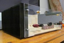
Here is the case I made for a line stage cathode follower tube preamp .
Its not the prettiest case in the world .
I used a piece of Baltic birch plywood for the base .
This allows what I call the " Audio Note " method - allowing boards to be changed around .
Used 4-40 x 1 " stainless steel machine screws which thread beautifully into the Baltic birch plywood .
The nylon spacers are mouser part no . Keystone 534-878
Also , note the hex cap screws , holding on the face plate , thread into a hardwood like walnut beautifully .
If ever cutting polycarbonate , please take note of the advise above .
I don't know the details of these accidents , but clearly the polycarbonate sprung back .
I seem to recall something in physics about potential energy transferring to kinetic .
A few other comments
a DC path between the heater and cathodes . Otherwise I've read there can be oscillation .
In other words , the heaters can't be left floating wrt to the cathodes .
But the second that the heater ground is connected to that beautifully clean analog ground
the heater ground will add noise - so try separating the 2 grounds with a resistor maybe 10K or 47K .
I need your advise concerning biasing 6922 ( e88CC ) .For a cathode follower , using both triodes in the tube ,
do you have a preference for the plate voltage and bias current ?
I have two Belles power amps one with a 1,000 VA transformer and the other with a 2,000 VA transformer .
Without a cap connected between the 2 hot connections of the power switch ,
you can see the spark when the amp is switched on .
However , for a tube preamp , there is no need for this cap .
Here is the case I made for a line stage cathode follower tube preamp .
Its not the prettiest case in the world .
I used a piece of Baltic birch plywood for the base .
This allows what I call the " Audio Note " method - allowing boards to be changed around .
Used 4-40 x 1 " stainless steel machine screws which thread beautifully into the Baltic birch plywood .
The nylon spacers are mouser part no . Keystone 534-878
Also , note the hex cap screws , holding on the face plate , thread into a hardwood like walnut beautifully .
If ever cutting polycarbonate , please take note of the advise above .
I don't know the details of these accidents , but clearly the polycarbonate sprung back .
I seem to recall something in physics about potential energy transferring to kinetic .
A few other comments
- In my opinion , its best to connect shielding to analog ground - not hydro earth .
- The 4th order LPF on the + B and - B supply .
- Also , one trick I discovered . Image a beautifully clean analog ground .
a DC path between the heater and cathodes . Otherwise I've read there can be oscillation .
In other words , the heaters can't be left floating wrt to the cathodes .
But the second that the heater ground is connected to that beautifully clean analog ground
the heater ground will add noise - so try separating the 2 grounds with a resistor maybe 10K or 47K .
I need your advise concerning biasing 6922 ( e88CC ) .For a cathode follower , using both triodes in the tube ,
do you have a preference for the plate voltage and bias current ?
Attachments
Last edited:
Nice work there. Yep, big toroids have a large inrush current but if you can charge the reservoir caps slowly, IE delay start it helps.
Re cathode followers I don't really use them unless on an AB2 amp, I prefer to use something like a 12BH7/6CG7/ECC99 as a LTP, cathode CCS from a negative rail. The ECC88 is a low gain valve so bias it at about 4mA or more, if your connecting both triodes in parallel, even better, twice the current. Re anode V, you don't need anything mad, 200 - 250v. You can't beat Merlin's guides on his site - http://www.valvewizard.co.uk/dccf.html which covers the basics.
Re valve heaters etc, AFAIK all electrodes should be connected to something, IE not left floating, if you ground the heaters do it away from input stages, so, as near as poss to chassis/C1 ground. I've not tried doing so through a resistor higher than a few hundred ohms, so can't comment. I attach a short article on the subject.
You've some good tips there on fettling, thanks.
Andy.
Attachments
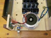
Apologies for the delay . Here is my second go at making a power amp case .
A few points of interest
So take what I've done and improve it .
A few points of interest
- Note how the heat sinks are raised up about 10mm above the table , allowing ventilation underneath the heat sinks .
- There are 4 holes in the Baltic Birch Plywood , 15mm diameter , allowing ventilation inside the amp .
- Heat Sinks are at the back , allowing shorter lengths for the +Ve , - Ve , Amp Out and Speaker Gnd wiring
- Feet are from Home Depot
- the back plate is polycarbonate - spec's say it does not start to get soft until 115oC
- Note the RCA's allow removal from the back - so a complete amp and heat sink can be removed and tested , without unsoldering an RCA .
- Note the trick of taping a 8 - 32 machine screws into hardwood to hold on the face plate
- L and R side are insulated from each other
So take what I've done and improve it .
Attachments


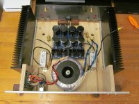
A few more comments
.
- Metal retailers will often sell aluminum that is scratched - so something to watch out for when buying the face plate
- The power switch I had has machine screws - It would have been easier if it had push on disconnects
- I'm concerned the Chokes will pick up EMI - so the diodes selected used have the backs floating
- The anode or cathode is not connected to the back , so the heat sinks don't end being noise transmitting antennas .
- Note the DIYAudio stores V3 power supply board require a specific pin out for the diodes
- Used a Bourns 8120 RC common mode choke for the Fo Felix EMI filter , but IMO this choke needs potting https://www.mouser.ca/datasheet/2/54/8100_series-777217.pdf
- There are epoxies made specifically for potting , but I used Lepage's PL ... not hot glue .
- Having reamer taper is really useful to have tight fitting hole diameters for the power switch and binding posts
- https://www.princessauto.com/en/t-handle-tapered-reamer/product/PA0002910254
.
Attachments

Last edited:
- Home
- Amplifiers
- Solid State
- Building your own amplifier enclosure