Actually i kind of like it being named Tower of Babel, unified people unified language, kind of what music is and work on this dac represent.
Of course, as long as it stays within the constrains of a normal case. Which shouldn't be an issue with this dac.
Of course, as long as it stays within the constrains of a normal case. Which shouldn't be an issue with this dac.
Tower.Ahaha, whatever I'd want, I couldn't.... there is no ground! 😊
Bab El Ich-Tar... maybe!
Bab El Ich-Tar... maybe!
Last edited:
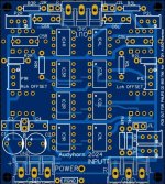
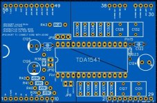
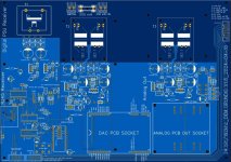
For TH lovers, I personally could share the entire project of my MODULAR DAC, I believe that the big advantage is that of being able to change both the dac chip module (with some modifications on the PSU) and the analog output stage (currently 3xAD844 per channel).
If you are interested I can attach the Json files (EasyEda).
Perhaps it could be a good starting point for a DAC that also includes balanced I2S (RJ45) input and optional Bluetooth.
As a SPDIF receiver I used an AK4113 card which I connected to the DAC obviously in I2S.
As for the DEM I used the "simple" Grundig technique.
The TDA also works in SIM mode via SAA7220 to CPLD converter
published a few pages back.
Sorry for my english!
Antonio
https://it.aliexpress.com/item/1005002922474547.html
Attachments


Nah, that will be soonish as another thread
Shall we cancel the "optimum TDA PCB" project and re-designate the project and start a new thread?
THUMBDAKIT
THe Universal Multi Bit DAc KIT
Designed as multiple PCB's/modules intended to fit a standard 430mm X 320mm HiFI enclosure
The TDA1541 plugin module would continue in discussion here and at the new thread and could also be incorporated into a more complete TDA1541 DAC with more TDA1541 Specific optimisation.
Thor
Even if not exactly for a normal case...Of course, as long as it stays within the constrains of a normal case.
May be of interest
Creating an Advanced PCB Stack-up Design for Noise Reduction

Granted I’m a complete passenger on this bus, and as such don’t have a say on what the destination is….Shall we cancel the "optimum TDA PCB" project and re-designate the project and start a new thread?
But if there was any passenger vote, I’m still in search for the ultimate reference tda1541a implementation, without any compromises (such as modularity, other IC’s etc… and I would like to think I’m not the only one given this thread being active for almost 20 years now
Nah, it should still be uncompromised dac. It deserves it. And it's become so rare to purchase as a dac chip, that it make no sense otherwise, it won't be reprodused as much as ad1862, ad1865 per se. Modularity in this case is to have multiple choices for this ultimate dac itself. Mainly different output stage, and the dac modular board (single, dual, 50hz dem mod but with expensive pmlcaps stacked to 110uf).Shall we cancel the "optimum TDA PCB" project and re-designate the project and start a new thread?
Also one thing we didn't take into consideration. Master clock with better crystals, and use usb board as slave.
In no way modularity geopardises "ultimate" implementation. If nothing else, it improves the very notion of it. Makes it cheaper as the bulk psu board needs no 8 layers. 8 layer board is much cheaper in smaller dimensions, so what really needs it (dac chip and close proximity surroundings), is made at small cost, and quite frankly easier to solder. Output stage, suites to tastes, and gives you what opamps in general bring to the table, rolling but rolling of discrete output stages. As undoubtly, people will make different discrete output stages, in future even better than the ones we come up now. Digital side can be tinkered with, with digital modues and test firsthand what works better, also saving cost if something goes south, so no need to reorder entire board, solder, resolder, etc. There is much to be gained, and not so much if any to be lost. There are drawbacks to it of course, it will take more time and effort to create such complex pcb.ultimate reference tda1541a implementation, without any compromises (such as modularity
@ThorstenL thanks for sharing your knowledge and insights here. The one thing I don’t understand is why some of the ideas have not been seen in any previous implementations of the tda1541.
For example the insight the current flows e.g. into the -15v rail, and the implications on the concept of ‘GND’.
You would think that some of the engineers of the past (Ken Ishiwata, Philips own engineers, others) maybe have given a phone call to their friends in the Philips Semiconductors (my former employer) engineering department and would have figured this out too… yet no previous implementations show this insight… surprises me…
Hi there are some PDFs about the DEM pins Fo calculations according to @ThorstenL proposed.
It is from the MatCad software, if Someone want to have I can post .mcd files.
(But it is not so complicated could be done with Excel?)
.
Please take a look for eventual mistakes?
Thanks
.
I also was interested how it reacts for TDA1540 dac, 14 bit dac, with 10 dem bits, same Iref and higher V@Cmsb.
And compare to typical value that most manufacturers used.
.
It is without a "grouping" values that can be added latter...
.
I just have one question about something that is not quite clear?
What is:
"We need to consider the worst case peak-peak ripple current, which is Iref / 4 * 10%."
and
"We need the variation from the ripple current
( 2.5% of 2mA worst case )"
.
I am asking because, booth sentences giving the same result, but in first we can consider peak-peak ripple current as Iref / 4
and in second sentence, peak-peak ripple current is Iref but % are divided by 4?
What is the real value of peak-peak ripple current?
Attachments
Last edited:
Maybe we need a POC ? First : swithcing on Thorsten's core layout decoupling to see how it works and sounds (without the complex I/V and front end) ?
Thorsten, when do you plan to power on th everroboard with a R1, story to see if if works as cd players there cost few bahts ? Before we focus on the ssuit of the concept...
Thorsten, when do you plan to power on th everroboard with a R1, story to see if if works as cd players there cost few bahts ? Before we focus on the ssuit of the concept...
@ThorstenL thanks for sharing your knowledge and insights here. The one thing I don’t understand is why some of the ideas have not been seen in any previous implementations of the tda1541.
For example the insight the current flows e.g. into the -15v rail, and the implications on the concept of ‘GND’.
You would think that some of the engineers of the past (Ken Ishiwata, Philips own engineers, others) maybe have given a phone call to their friends in the Philips Semiconductors (my former employer) engineering department and would have figured this out too… yet no previous implementations show this insight… surprises me…
Surprises a lot of people too , especially for those who invented and created the TDA , but anyhow next future will tell us about ......
.
From this diagram MSB Iref is 2mA so the percentage correction is 2.5%What is:
"We need to consider the worst case peak-peak ripple current, which is Iref / 4 * 10%."
and
"We need the variation from the ripple current
( 2.5% of 2mA worst case )"
.
I am asking because, booth sentences giving the same result, but in first we can consider peak-peak ripple current as Iref / 4
and in second sentence, peak-peak ripple current is Iref but % are divided by 4?
What is the real value of peak-peak ripple current?
.
But this is when the Cs are connected to "GND" not to the "-15V"?
Maybe the voltages trough the DEN oin Cs shoud be considered according to the connection in -15V?
Anyway
The results for C in the PDFs are good, percentages shuld be divide by 4 😎
I will correct it and re-post
What is:
"We need to consider the worst case peak-peak ripple current, which is Iref / 4 * 10%."
and
"We need the variation from the ripple current
( 2.5% of 2mA worst case )"
.
I am asking because, booth sentences giving the same result, but in first we can consider peak-peak ripple current as Iref / 4
and in second sentence, peak-peak ripple current is Iref but % are divided by 4?
What is the real value of peak-peak ripple current?
The first case states the mathematical rule for the worst case ripple current on exact TDA1541 DEM Filter pin, illustrating the logic, that is each current splitter output is Iref +/-5% but all Iout summed must be equal to Iref.
The second case is simplified for a specific pin with a specific current value, simplified to be used in next round.
The real value of ripple will vary from IC to IC and pin group to pin group. It could be even that there is no difference with some IC's and pins.
The +/-5% number BTW is from RvdP paper on the TDA1540 prototype. It should represent the worst case. Actual production TDA1541 may be better (or not).
In the 80's Chip making was still more alchemy and magik than reliable tech and science the way it is now, with deep UV or extreme UV lithography.
Thor
Last edited:
Maybe we need a POC ?
POC = Piece of Carp
Thorsten, when do you plan to power on th everroboard with a R1, story to see if if works as cd players there cost few bahts ? Before we focus on the ssuit of the concept...
I have 3 Sony players with non-A chips. It will be a while, I'm hoping before X-Mas.
Thor
But this is when the Cs are connected to "GND" not to the "-15V"?
We normally assume power supplies are 0 Ohm DC to Light, so naturally connecting the capacitors to AGND or -15V makes zero difference in this theory and in theory there is no difference between theory and practice.
Maybe the voltages trough the DEN oin Cs shoud be considered according to the connection in -15V?
Voltage is "across", not "through" capacitors.
Thor
Voltage is "across", not "through" capacitors.
Yes off course - but that is what is somehow unclear...We need the variation from the ripple current (2.5% of 2mA worst case) cause less voltage variation across C0 (MSB Cdem) than 1/2 MSB respective to the nominal voltage across C0, which is ~7.5V.
I have 3 Sony players with non-A chips. It will be a while, I'm hoping before X-Mas.
Unfortunately for me I dont have any old CD player to pull-out chips 🙁Make a big mother board, add DAC daughter boards for the really common DAC's (PCM56, TDA1541 etc.) found in cheap old players and sell the tested PCB's, customer savages the Chips from the CDP and plugs them into the sockets, configures jumpers and voila, Bob's your Uncle and Donny POTUS.
.
But I was remember a time that with good old Marantz CD-94, CD-94 MK version with 2 x S1, classic Philips CD304, CD880 some relly good Revox models with tda1540... Almost 30 years ago... 🙁
...
Anyway, I still have some new pieces of '41A and '40 too, about the same time acquired from the stores and sufficient to throw out, factory pro spare parts "S2" versions from local radio stations. When nobody wanted 😡 these "obsolete" dac chips...
Thanks for the explanation...makes zero difference in this theory and in theory there is no difference between theory and practice.
Sorry it is not clear enough this about IrefThe first case states the mathematical rule for the worst case ripple current on exact TDA1541 DEM Filter pin, illustrating the logic, that is each current splitter output is Iref +/-5% but all Iout summed must be equal to Iref.
The second case is simplified for a specific pin with a specific current value, simplified to be used in next round.
The real value of ripple will vary from IC to IC and pin group to pin group. It could be even that there is no difference with some IC's and pins.
The +/-5% number BTW is from RvdP paper on the TDA1540 prototype. It should represent the worst case. Actual production TDA1541 may be better (or not).
In the 80's Chip making was still more alchemy and magik than reliable tech and science the way it is now, with deep UV or extreme UV lithography.
The values are from the datasheets
.
That is for the full scale currents, zero scale currents and output voltage compiliance
Note that ratios of permited Voc values are the same as Ifs. and it is 3 :1
.
I persume that Iref from the picture abowe
is the same = 4mA
Last edited:
- Home
- Source & Line
- Digital Line Level
- Building the ultimate NOS DAC using TDA1541A