74LVC74 is 250MHzThe rest (7474, 74HC74, 74HCT74, 74LS74, CD74HC74, etc. all are around 25 to 30 MHz max. clock freq., not interesting for us.
It is 100 MHz according to TI's data sheet, but 3.3 V and not DIP. F or S look like the best options for our purpose.
I have built+listened to many many DAC chips (same peripherals), but there is something special about the TDA15xx.
Done right, it is extremely smooth, effortless and "analog" sounding.
Yes, precisely.
It is the only Dinosaur I know built on diff ECL + emitter scaling.
FET's 0
BJT's many 1kU
Is that the reason why it sounds different than newer CMOS, high sample rate DACs?
I wish I knew for sure. The only other DAC like it is TDA1540 and as it shares almost the precise internal circuit in an earlier incarnation, it may be unsurprising that it sounds very similar.
It would be my take that the Current Mode Logic and Bipolar switching are responsible.
The only other DAC I know that is as legendary as the TDA1540/41 CDP's/DAC's is the Accuphase DC-81 (and related). That uses 4 or 5pcs 4-Bit
bipolar current switches to make in effect a discrete DAC, not R2R but binary weighted:
Discussed here: Information wanted about Accuphase DP-70 DAC: 4 pices Intersil's 4-bit ICL 8019ACPD
Hint, something like that could be added to a TDA1541 to give it more than 16 Bit (with ~110dB SNR it is nearly 18.5 Bit capable IN PRINCIPLE anyway).
It also shows a technique by which a second TDA1541 could be stacked for a 32 Bit DAC with 18.5 Bit ENOB.
Finally, if we use 8pcs parallel/balanced TDA1541 for the MSB's (staggered for 768kHz compatibility) we expect around 119dB (> 19.5 Bit) SNR and adding two more TDA1541 for the LSB's gives us a 32 Bit DAC based around 10pcs TDA1541.
With genuine equipment pulls now running into 100 USD++ making something like this with 10pcs TDA1541 per DAC is unlikely to be feasible. What a shame. Just imagine, a DAC drawing around 9W just for DAC IC's... And another 9W for the shunt regulators.
Before I left ifi/AMR around 1,000 pcs Taiwan S1 were in Stock somewhere in the "Wherehouse", that could have made 100 pcs "super special edition" DAC's, but nothing ever came out of this. I suspect the IC's are still in the godown.
Thor

But its sound IME has a lot to see with how you decouple the power supplies pins... But there is no doubt the latest production (Asia) had a cleaner, less smooth but still analog (imho the latests are more "fidel", while the european made are more forgiving on bads recordings and less well executed cd players/DAC))
I find even with oversampling, SAA7220 and "standard Philips/Marantz" implementation TDA1541 have this distinct sound. Just less so.
Thor
74AUP1G74 is 90 MHz (3.3 V logic!)
74AUC74 at 2.5V (so compatible with a TTL to PECL translator) is rated for 350MHz.
https://www.ti.com/lit/ds/symlink/sn74auc74.pdf
I may have gotten AUP and AUC mixed up.
74AUC is very fast, low voltage, but TTL compatible and it uses a special kind of "soft" switching to limit ground bounce.
AUC Little Logic devices provide 8-mA dc drive current at the 1.8-V VCC node for nonportable applications, while maintaining the signal-integrity performance of a 4-mA dc driver. The ULTTL output used in the AUC Little Logic family is designed to address each of the three critical performance requirements previously noted. Figure 1 shows a schematic of the ULTTL output structure.
To achieve the three impedance phases, the ULTTL output utilizes a three-branch p-channel upper-output (UOP) and three-branch n-channel lower-output (LOP) structure (see Figure 1). For the purpose of illustration, the three branches are referred to in this application report as the ac branch (ACB), the transmission-line branch (TLB), and the dc branch (DCB).
The first branch, which uses the diode in the output structure, provides the high dynamic current required to drive through the ac threshold.
The second branch, which contains a series resistor, provides optimized impedance matching into the transmission line.
The third branch provides the additional dc current drive for applications requiring more than 4 mA of output drive current at 1.8-V VCC.
Each independent branch posses a unique on-state resistance (ron). As the output transitions from a low to high (or high to low), the equivalent resistance of all branches varies in a controlled manner by adjusting the individual resistance of each branch. The low-to-high transition functions similarly to the high-to-low transition. The output impedance is controlled during the low-to-high transition sequential action outlined below and shown in Figure 2.
1. During the initial phase of the transition, all three legs are turned on. The parallel ron of all three legs provides very low combined impedance.
2. During the second phase of the transition, the ACB and DCB are turned off, and the output transitions to a higher impedance. As the output voltage level approaches VCC, the series diode begins to saturate and, eventually, becomes reverse biased, causing the current through the ACB to be reduced to less than 1 mA (basically, turned off). A threshold-controlled feedback circuit turns off the DCB. The thresholds are adjusted, to minimize the effect of oscillations directly at the output of the driver before entering the transmission line. (NOTE: A major advantage for the DCB being turned on in the initial stage is to provide support for the ACB at lower VCC ranges where speed often is sacrificed.) The TLB ron is 50 Ω to 65 Ω and, because it is the last branch remaining on, it provides the impedance matching to the transmission line.
3. In the final phase of the transition, the DCB is turned on by the threshold-controlled feedback circuit to provide a combined DCB and TLB equivalent resistance that is satisfactory for driving applications requiring more than 4 mA of output drive current at 1.8-V VCC.
In practice:
Testing 74AUC with an 8 GHz Sampling Oscilloscope
The core part I'd want to use for IIS2SIM is this:
Mouser 595-SN74AUC16374DGVR
One IC makes a 16 Bit shift register and handles 250MHz.
Thor
Last edited:
Thanks @TL 👍. . . . I wish I knew for sure. The only other DAC like it is TDA1540 . . . . . .
Is this chip still worth a try in 2024?
TDA1541?
Well, if all you listen to are native DSD & 768kHz/32 Bit recordings, no.
Thor
Thorsten, where did you find this information? 👍. . . . . The only other DAC I know that is as legendary as the TDA1540/41 CDP's/DAC's is the Accuphase DC-81 (and related) . . . . .
View attachment 1349218
Actually it is opposite - I reached tha page when i was directing from forum link. 🙂There is a feature in almost all forums that truncates web addresses for layout convenience. Perhaps your browser is not able to direct you correctly from those.
Try this (or copy & paste)
I could not open the same page navigating trough their site... 🙁
Strange?
Thanks & Cheers 🙂
Hi
@ members prototyping PCB for TDA1541A:
What other modules will be on the PCB among new way of decoupling?
Thanks
@ members prototyping PCB for TDA1541A:
What other modules will be on the PCB among new way of decoupling?
Thanks
Somebody asked about power supply with lower values of capacitors. (As a complement to one with super-capacitors - battery concept.)
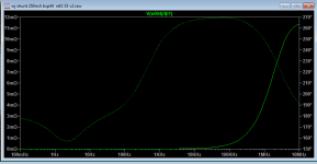
I finished power supply. The version with small values of capacitors. But very effective.
The color of the traces are match with probes in the PDF.
I know that this output impedance sounds as imposibile 🙁 but that is that... 🙂
I used few models to compare and with all of them results are very close.
PSpice models are attached. For LT spice users read the comments in lines how to adopt simple sintax for LT it is about AREA parmeter in one of the models.
.


.
I finished power supply. The version with small values of capacitors. But very effective.
- Extremely low output impedance.
- Very good PSRR
- Relatively simple (modules are repeating...)
- Very adoptable, values can change, override some components etc.
- No special parts, exept very low ESR few components absolutely needed for the best chrs.
- Could be used as separate PCB with reasonably short connections because of the shunt operation end...
The color of the traces are match with probes in the PDF.
I know that this output impedance sounds as imposibile 🙁 but that is that... 🙂
I used few models to compare and with all of them results are very close.
PSpice models are attached. For LT spice users read the comments in lines how to adopt simple sintax for LT it is about AREA parmeter in one of the models.
.
.
Attachments
Last edited:
@ Zoran , why would an almost zero millihoms output impedance will be better ( sound wise ) than an 10 to 20 milliohms one ( like the series regs ) , and does it still true with lipo battery supply having milliohms impedance ?
.
.
@Zoran, Why return to TL431 as a reference? Aren't there better ones today? The Walt Jung references that I use in my regulators are incomparably better than the TL431. Also, all CCS can be performed with depletion mosfets with much better results and at the same time it will simplify the circuit.
btw ,here is an example, shunt reg with depletion mosfets ,ADA4897 and GLED431 reference
btw ,here is an example, shunt reg with depletion mosfets ,ADA4897 and GLED431 reference
Attachments
Last edited:
Hi it is not about "better", actually other party imputing a "better" implicate that it from first party referencing - is "better"?@ Zoran , why would an almost zero millihoms output impedance will be better ( sound wise ) than an 10 to 20 milliohms one ( like the series regs ) , and does it still true with lipo battery supply having milliohms impedance ?
.
.
It is discrete design with an elements in the ara of the DAC chip produced. It seems somehow logical to use these parts to find out what could it be that they used with TDA or other dac from the same era... 🙂
.
And I said it is not against ot opposing the battery or supercap aproaches - only a complement.
ok , let say it's a different way to do it , listening to the TDA i think it is from no era , this guy is out of competition , came out from genius guys mind for our pleasure till today 🙂
.
.
Last edited:
Hi@Zoran, Why return to TL431 as a reference? Aren't there better ones today? The Walt Jung references that I use in my regulators are incomparably better than the TL431. Also, all CCS can be performed with depletion mosfets with much better results and at the same time it will simplify the circuit.
btw ,here is an example, shunt reg with depletion mosfets ,ADA4897 and GLED431 reference
GLED is OK but it is "fixed" for 2.5V as zener part. And it needs special part LED to achieve that good performance. And low noise zetex BJT. (But off course that we can stack 2 x for 5V sequence i prsume? Even tried in spice...). I made it with 431 in "special" way because it is simple and available. And most of that it is adjustable to various potentials and different power suplies. Can be pretty much universal?
I tried it in praxis, this 3 part, (passive LC - simple PreRegulator - shunt). And it sounds very good.(I already tried in some preamps and DACs sa well.)
And 431 is only IC (with small number of BJTs inside) so it "can go" as discrete 😡.
Thanks 🙂
- Home
- Source & Line
- Digital Line Level
- Building the ultimate NOS DAC using TDA1541A