Hi luxury54,
Was the 0.01uF (C1) still in series with one of the the 10K resistors?
The DEM circuit only works when both clock signals are DC-coupled to the resistive attenuator. This is required for achieving correct DC bias voltage at pin 16 / 17 (approx. -11.85V).
I took both the normal and inverted clock signal directly from the AD comparator
Was the 0.01uF (C1) still in series with one of the the 10K resistors?
The DEM circuit only works when both clock signals are DC-coupled to the resistive attenuator. This is required for achieving correct DC bias voltage at pin 16 / 17 (approx. -11.85V).
Hello EC
No,i took out the 0,01uF capacitor that was after the comparator,I only left the 47 ohm resistor on both AD comparator's outputs.
So I don't know why was I experimenting such distorsions - perhaps the inverted signal of the AD is not symetrical to the non-inverted one? what could be the explanation?
Anyway ,after inverting the 5,8 Mhz clock with a 74HCT04 and feeding the DEM pins I experienced very good details,resolution and crisp highs.
Thank you EC for all your precious advices!
Re: Re: Speaker attenuation experience
Hmmm...maybe I could then get rid of volume control AND active 2 way crossover for my Tannoy Autograph's 15'' coaxials if I add one speaker attenuator for each of the four channels (flattening response and output volume) and adequate passive filtering of the input signal on my power amps???
Too complicated maybe...not for me but for my children... 😀
Please advice, guys...
I have to test the simple mono system ASAP.
Regards,
M
a333bt said:
Hi Zero One, John
i had similar experiences.
It is easy to test how speaker attenuator works.
I tried with 100 ohms 3-4W mono wirewound potentiometer. Just connected between speaker + terminal and speaker cable.
Thats it.
Sound is MUCH better compare to volume control unit with Vishay bulk foil resistors.
Even in low levels sound is full, live, clean, especially dynamic is increased.
So in future i would go for remote relay speaker attenuator with Mills 5W noninductive resistors.
Thanks Zero One and John for sharing experiences.
I now what John put on thread is based on many measurents, listenings, also brothers sugestions with his experiences of living concerts.
It concern also DEM mods and attenuator for DI4T, which works really good.
😀
Hmmm...maybe I could then get rid of volume control AND active 2 way crossover for my Tannoy Autograph's 15'' coaxials if I add one speaker attenuator for each of the four channels (flattening response and output volume) and adequate passive filtering of the input signal on my power amps???
Too complicated maybe...not for me but for my children... 😀
Please advice, guys...
I have to test the simple mono system ASAP.
Regards,
M
how to implement Johns volume control on Linkwitz Orions
4 way Active with 4 Stereo ASKA amps on the main speaker and 4 mono mosfet 350w amp modules of 4 x Thors.
impossible I guess, I think I would be best to look at variable I/V volume solution.
any thoughts?
I think 2 ways might be possible, but 4 way.........
4 way Active with 4 Stereo ASKA amps on the main speaker and 4 mono mosfet 350w amp modules of 4 x Thors.
impossible I guess, I think I would be best to look at variable I/V volume solution.
any thoughts?
I think 2 ways might be possible, but 4 way.........
Hi Max
Yes there is a problem balancing a whole bunch of attenuators, in my case I have two per side, and only stereo so it is fairly manageable. In fact the ability to tune high and lows volume wise independently is actually pretty good if I need to tailor for a particular recording.
Ideally what is needed is some sort of ganged control (ie on the same shaft) which can be fine tuned by adjusting the relative position of each and then locking them together, my experience is that the treble/bass and stereo balance remain pretty much constant across the range of listening volumes so that would work. But no such device exists, it would have to be fabricated somehow from other bits. There are stereo power attenuators available, I guess that could be a starting point.
Ultimately ECs idea of relays and resistors is probably the way to go, but I imagine the bulk and cost will be high.
Control at the I/V end is probably a fine approach, but is suspect not ideal, and in my case the system is working with a phono amp (non attenuated) as well and it would be good to apply the concept to all inputs if possible.
ECDesigns has mentioned that control the IV volume was possible but the better solution is at the attenuator after the amp. However, that needs relay circuit to avoid power up/down thumps.
Recently I run into some hum / hissing problem with the simple IV and I only discover this when I tried it on my fren's setup. There is a clicking noise of less than 1second interval.
I wonder if the following will work
for the trans IV output,
floating charge transfer -> capacitance multiplier -> LM3X7 -> Super Shunt -> transimpedance ..
Thanks Zero One.
I had the same impressions you commented.
I've seen some control boards with 8 relays with potential for remote control, probably the same approach EC has taken.
I think it is better to implement it on the speaker's end instead of the amp's end, to increase signal to noise ratio, right?
Regards,
M
I had the same impressions you commented.
I've seen some control boards with 8 relays with potential for remote control, probably the same approach EC has taken.
I think it is better to implement it on the speaker's end instead of the amp's end, to increase signal to noise ratio, right?
Regards,
M
attenuate the BCK in PCM2706
Hi Max,
Do you attenuate the BCK in your USB PCM2706 same as WS/DATA?
Thanks
Hi Max,
Do you attenuate the BCK in your USB PCM2706 same as WS/DATA?
Thanks
Hi 2A3SET,
No, I use about 10% the values of DATA, WS. Please note that they are hardly ideal values. I just stopped searching when they did produce good sound. From memory:
DATA, WS:
signal series R= 1K2. Attenuator to VCC= 3K3. Attenuator to ground=680R. I have to try a choke here.
BCK:
Signal= 220R SMD. Attenuator to VCC= 330R + DIY choke. Attenuator to ground = 110R. I am not so sure about series R now...but it works 😀
Hope it helps,
M
Hi 2A3SET, No, I use about 10% the values of DATA, WS. Please note that they are hardly ideal values. I just stopped searching when they did produce good sound. From memory: DATA, WS: signal series R= 1K2. Attenuator to VCC= 3K3. Attenuator to ground=680R. I have to try a choke here. BCK: Signal= 220R SMD. Attenuator to VCC= 330R + DIY choke. Attenuator to ground = 110R. I am not so sure about series R now...but it works
Sorry 2A3SET, I checked it and I am using not 330R but 681R from attenuator node to VCC on the BCK path. Series resistor is indeed 220R.
Hi EC,
I just finished to add a quatrifillar DIY choke to the four DATA and WS attenuators of my DI4 ( the nonscrambled one), one coil for each DATA/WS pair from each DAC chip. I respected connection for each supply> inverting v/s non inverting. As I winded it alone I only reached 2,6R DC (32AWG), about 5 meter length on a toroid. Now I have to add BCK choked attenuators but I hope some son will help me wind it and reach higher RDC.
I love this DAC because it has bass depth and midbass punch and dynamics which makes it a great source for parties (well, tonight I have a party
 ) but lacked refinement of my others DIDACs or D1M. With the present mod it is sounding really more subtle and some grain disappeared (even if I only use 50ppm, 0.6W resistors), maintaining its good qualities. I hope the next mod consisting on quatrifillar choke on attenuated BCK will improve further the sound. 😎
 Thanks John,
M
Hi maxlorenz,
In the SD-player I use separate chokes for DATA and WS (10mH each). These chokes are connected in series with the 3K3 resistors that connect to VCC. The function of these chokes is to attenuate power supply noise, preventing it from entering either DATA or WS input. The noise from the I2S source is attenuated, but you could also experiment with suitable LC filters (check timing).
All noise and interference entering the DAC I2S inputs will end up on the output signal, and affects timing jitter at the moment of on-chip D/A conversion. It mainly affects micro detail and soundstage background.
For BCK I use no chokes, but the dynamic jitter attenuator (post #2853).
Why adding a dynamic jitter attenuator?
The master clock always produces jitter, however so small, next the clock signal passes some circuits before ending up at the BCK input (clock buffers, flip-flops, counters, wiring) and each component adds extra jitter (cumulated jitter). This would still prevent obtaining a low jitter signal at the BCK input. The dynamic jitter attenuator corrects this to some degree, ending up with timing jitter at the BCK input that could be lower than the master clock jitter.
The circuit is in post #2853, you may have to tune 470 Ohm resistor in order to get approx. 1.2V across it. Dynamic jitter attenuation can be fine tuned by varying 220nF after the exact resistor value has been determined. The resistor value depends on clock signal amplitude and average duty cycle (usually 50%).
This BCK attenuator extracts a DC bias voltage (generated across 220nF) that varies with BCK duty cycle (jitter). The Schottky diodes prevent discharging the 220nF below approx. 1.2V as the BCK signal goes low. The RC time constant (220 Ohm ... 1K and 220nF) determines exact correction factor and needs to be tuned to best audible performance. This way the exact moment of triggering can be adjusted depending on momentary BCK duty cycle. Corrections are extremely small but effective.
Other factor is highest on-chip clock frequency as this determines ground-bounce levels. The TDA1543 in the SD-player now runs on minimum possible frequency of 1.4112 MHz. In order to do so, the Philips I2S signal had to be modified to 32 bits / frame (16 bits for L channel immediately followed by 16 bits of R channel). This effectively halves the bit clock rate while maintaining 44.1 KHz sample rate.
I hope the next mod consisting on quatrifillar choke on attenuated BCK will improve further the sound.
In the SD-player I use separate chokes for DATA and WS (10mH each). These chokes are connected in series with the 3K3 resistors that connect to VCC. The function of these chokes is to attenuate power supply noise, preventing it from entering either DATA or WS input. The noise from the I2S source is attenuated, but you could also experiment with suitable LC filters (check timing).
All noise and interference entering the DAC I2S inputs will end up on the output signal, and affects timing jitter at the moment of on-chip D/A conversion. It mainly affects micro detail and soundstage background.
For BCK I use no chokes, but the dynamic jitter attenuator (post #2853).
Why adding a dynamic jitter attenuator?
The master clock always produces jitter, however so small, next the clock signal passes some circuits before ending up at the BCK input (clock buffers, flip-flops, counters, wiring) and each component adds extra jitter (cumulated jitter). This would still prevent obtaining a low jitter signal at the BCK input. The dynamic jitter attenuator corrects this to some degree, ending up with timing jitter at the BCK input that could be lower than the master clock jitter.
The circuit is in post #2853, you may have to tune 470 Ohm resistor in order to get approx. 1.2V across it. Dynamic jitter attenuation can be fine tuned by varying 220nF after the exact resistor value has been determined. The resistor value depends on clock signal amplitude and average duty cycle (usually 50%).
This BCK attenuator extracts a DC bias voltage (generated across 220nF) that varies with BCK duty cycle (jitter). The Schottky diodes prevent discharging the 220nF below approx. 1.2V as the BCK signal goes low. The RC time constant (220 Ohm ... 1K and 220nF) determines exact correction factor and needs to be tuned to best audible performance. This way the exact moment of triggering can be adjusted depending on momentary BCK duty cycle. Corrections are extremely small but effective.
Other factor is highest on-chip clock frequency as this determines ground-bounce levels. The TDA1543 in the SD-player now runs on minimum possible frequency of 1.4112 MHz. In order to do so, the Philips I2S signal had to be modified to 32 bits / frame (16 bits for L channel immediately followed by 16 bits of R channel). This effectively halves the bit clock rate while maintaining 44.1 KHz sample rate.
Hi EC,
what is Your oppinion.
When using tda1541A with transimpedance style
dac after stage,
which is the good value of dc at the tr-imp-iv
(at the point of I input from dac)
for dac chip to meet.
thanks...
what is Your oppinion.
When using tda1541A with transimpedance style
dac after stage,
which is the good value of dc at the tr-imp-iv
(at the point of I input from dac)
for dac chip to meet.
thanks...
Dear EC,
Thanks for your input about dynamic jitter attenuation circuit.
As you describe it, the "fine tuning" of the capacitor and resistor values of the circuit will need "only" good ears an a good two channel scope?
A priori I do not think I could be able to perform the optimal tuning 😱
...hmm, or maybe yes...now that I re-read it... 🙂
Thanx,
M
Thanks for your input about dynamic jitter attenuation circuit.
As you describe it, the "fine tuning" of the capacitor and resistor values of the circuit will need "only" good ears an a good two channel scope?
A priori I do not think I could be able to perform the optimal tuning 😱
The circuit is in post #2853, you may have to tune 470 Ohm resistor in order to get approx. 1.2V across it. Dynamic jitter attenuation can be fine tuned by varying 220nF after the exact resistor value has been determined.
The resistor value depends on clock signal amplitude and average duty cycle (usually 50%). This BCK attenuator extracts a DC bias voltage (generated across 220nF) that varies with BCK duty cycle (jitter).
The Schottky diodes prevent discharging the 220nF below approx. 1.2V as the BCK signal goes low. The RC time constant (220 Ohm ... 1K and 220nF) determines exact correction factor and needs to be tuned to best audible performance. This way the exact moment of triggering can be adjusted depending on momentary BCK duty cycle. Corrections are extremely small but effective.
...hmm, or maybe yes...now that I re-read it... 🙂
Thanx,
M
Hi zoran,
DC voltage at the TDA1541A outputs should be below 25mV, but in practice (with the trans-impedance I/V converter) you can get away with DC voltages up to approx. 90mV.
No, it's just that my priority now goes to to the SD-player, because I need a suitable digital audio source first.
what is Your oppinion. When using tda1541A with transimpedance style dac after stage, which is the good value of dc at the tr-imp-iv (at the point of I input from dac) for dac chip to meet.
DC voltage at the TDA1541A outputs should be below 25mV, but in practice (with the trans-impedance I/V converter) you can get away with DC voltages up to approx. 90mV.
is this thread is come to the dend, or what
No, it's just that my priority now goes to to the SD-player, because I need a suitable digital audio source first.
Hi maxlorenz,
1) Adjust the resistor value until you measure approx. 1 volts across it. The resistor value depends on bit clock amplitude and duty cycle. With 5Vpp and exact 50% duty, R would be around 280 ... 300 Ohms.
2) Connect a scope across the resistor, make sure the circuit receives a 2.8224 MHz bit clock signal, now adjust capacitance until achieving lowest possible ripple voltage. With 300 Ohms, capacitor value would be around 100 ... 200nF.
Start with 280 Ohms and 200nF (2 x 100nF stacked foil cap in parallel).
As you describe it, the "fine tuning" of the capacitor and resistor values of the circuit will need "only" good ears an a good two channel scope?
1) Adjust the resistor value until you measure approx. 1 volts across it. The resistor value depends on bit clock amplitude and duty cycle. With 5Vpp and exact 50% duty, R would be around 280 ... 300 Ohms.
2) Connect a scope across the resistor, make sure the circuit receives a 2.8224 MHz bit clock signal, now adjust capacitance until achieving lowest possible ripple voltage. With 300 Ohms, capacitor value would be around 100 ... 200nF.
A priori I do not think I could be able to perform the optimal tuning
Start with 280 Ohms and 200nF (2 x 100nF stacked foil cap in parallel).
Thanks EC for your tips on post # 2916. 🙂
Dear Ccshua,
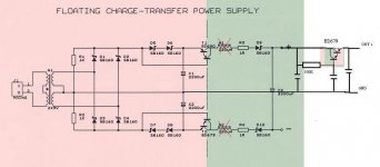
Both charge transfer circuits are brilliant. The floating one is supposed to be best.
Please remember that C3 will see double the voltage. You may consider attaching your regulator's "ground" to CT's V(-) to benefit from the floating approach.
Cheers,
M
Dear Ccshua,
Both charge transfer circuits are brilliant. The floating one is supposed to be best.
Please remember that C3 will see double the voltage. You may consider attaching your regulator's "ground" to CT's V(-) to benefit from the floating approach.
Cheers,
M
Hi EC,
I tried the other day the speaker attenuators with common ceramic power resistors just to have a taste of it, under worst circumstances...power R assorted as available, chipamp driven with probably clipping input, etc...I did hear some immediateness to the sound on midrange and highs but SPL was still low and bass was lacking. But good anyway to try on better scenario.
Then I thought that when using my TVC y only use three steps of volume level, each being 2db apart, so carefully selecting source, amp and resistor could use a few R...but, hey! TVC increases current as voltage goes down, just the opposite of a power R: could a transformer coupled attenuator work well at speaker level?
The core must not be big, since DC shall be low and VAC should be around peak output power, right?
What do you think?
I could order a custom winded TX locally, 8 Ohm DC primary and multiple secondaries.
They have to be system-specific, though...
M
- Home
- Source & Line
- Digital Line Level
- Building the ultimate NOS DAC using TDA1541A