I have been following this thread for a couple of months now, and am happy to see the pcb's and kits are already sold.
There is some confusion for me since apparently there are different types of I2S signals.
I have a simple question: Is there anyone who has already connected the DI8-NonosDAC with the cd-player from Philips CDPRO2M ?
Thank You, Frederik/Breda/Netherlands
There is some confusion for me since apparently there are different types of I2S signals.
I have a simple question: Is there anyone who has already connected the DI8-NonosDAC with the cd-player from Philips CDPRO2M ?
Thank You, Frederik/Breda/Netherlands
DI DAC PCBs
Hi elec-tron2
Thanks for your reply [post #1340]
All DI DAC prototype PCBs were hand made, the professional ones displayed in post 1336 were made by a PCB manufacturer (Europrint).
Hi elec-tron2
Thanks for your reply [post #1340]
All DI DAC prototype PCBs were hand made, the professional ones displayed in post 1336 were made by a PCB manufacturer (Europrint).
Hi frippen,
Thanks for your reply [post #1341]
Well, actally I haven't shipped any PCBs / kits yet. As soon as they are fully tested and partially assembled (SMD). I will inform everyone who either ordered PCBs / kits or asked to inform them when the PCBs were ready.
As for I2S, I answered that question a few times already. The DI DACs work directly with USB, plug and play.
When a external I2S signal is used, it needs to have the following specifications:
Philips format, 2's complement, 16 bits, 64 BCK/frame.
If the I2S source you are planning to use doesn't meet these I2S specifications (16 or 48BCK/frame), the interpolator doesn't work as planned, and taps need to be changed.
A solution to this problem, is using the universal I2S interface (translates I2S input signal to the required Philips format). The universal I2S interface uses SPDIF to extract data-only (not critical to jitter), and the transport's low jitter master clock for generating BCK. The universal I2S interface also offers a jitter reduction for SPDIF only sources (no master clock available), by means of a by-passable shift register reclocker.
I personally use the USB interface now, the sound quality is of such high level, I am more than pleased with it.
People are always welcome to come over and listen to the new DI DACs. DiyAudio members who already listened to the DI DAC early prototypes, only heard a fraction of what the new DI DACs are capable of, I even had to modify my audio set, so it could keep up with the significantly increased DI DAC sound quality
All new PCBs work!
Hi all,
Project update,
As you may have noticed, I have received the first batch of the professional DI DAC PCBs. I have been assembling and testing all PCB versions in order to make sure everything works flawlessly.
Well actually they do, I put all versions together and they worked straight-away. I haven't received the DI8 power supply and DI8 timing chain yet, so I had to use the prototype PCB's for now.
The assembly of the modules was straight forward, everything fitted flawlessly. It should be quite easy to assemble them. I enjoyed every minute of the assembly process.
I have also completed over 300 colour drawings containing detailed module assembly instructions, voltage checks and wiring diagrams. This should make assembly a piece of cake.
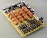
I will now post some photographs, showing the PCB quality. The PCbs have fully gold plated traces (not only the pads), the solder mask is transparent so the gold plating on the traces remains visible. The silkscreen print is in black.
Ok, let's start with the most interesting one for diy, the DI 16 core. The heatsinks used on the TDA1543 chips are standard copper chipset coolers from thermaltake, they are self-adhesive.
Hi all,
Project update,
As you may have noticed, I have received the first batch of the professional DI DAC PCBs. I have been assembling and testing all PCB versions in order to make sure everything works flawlessly.
Well actually they do, I put all versions together and they worked straight-away. I haven't received the DI8 power supply and DI8 timing chain yet, so I had to use the prototype PCB's for now.
The assembly of the modules was straight forward, everything fitted flawlessly. It should be quite easy to assemble them. I enjoyed every minute of the assembly process.
I have also completed over 300 colour drawings containing detailed module assembly instructions, voltage checks and wiring diagrams. This should make assembly a piece of cake.
I will now post some photographs, showing the PCB quality. The PCbs have fully gold plated traces (not only the pads), the solder mask is transparent so the gold plating on the traces remains visible. The silkscreen print is in black.
Ok, let's start with the most interesting one for diy, the DI 16 core. The heatsinks used on the TDA1543 chips are standard copper chipset coolers from thermaltake, they are self-adhesive.
Attachments
USBDI2S photographs
Hi all,
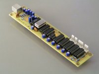
Next picture, the DI16 companion module, USBDI2S. It provides direct connection trough USB (no drivers needed), and also provides a DI2S input. The USBDI2S module automatically toggles between USB and DI2S digital audio source. The I2S signal derived from the PCM2706 USB chip, passes a shift register reclocker, greatly reducing phase noise / jitter. The I2S signals derived from the PCM2706 pass a double differential buffer to provide common noise rejection and to protect the PCM2706 chip I2S outputs.
The PCB-only option has all SMD components pre assembled / included. This includes the PCM2706 chip, all SMD resistors, UHS inverter for the shift register reclocker and decoupling caps.
Assembly is little fun, some IC sockets, electrolytic capacitors, connectors, resistors and two EMI filters, that's all.
Hi all,
Next picture, the DI16 companion module, USBDI2S. It provides direct connection trough USB (no drivers needed), and also provides a DI2S input. The USBDI2S module automatically toggles between USB and DI2S digital audio source. The I2S signal derived from the PCM2706 USB chip, passes a shift register reclocker, greatly reducing phase noise / jitter. The I2S signals derived from the PCM2706 pass a double differential buffer to provide common noise rejection and to protect the PCM2706 chip I2S outputs.
The PCB-only option has all SMD components pre assembled / included. This includes the PCM2706 chip, all SMD resistors, UHS inverter for the shift register reclocker and decoupling caps.
Assembly is little fun, some IC sockets, electrolytic capacitors, connectors, resistors and two EMI filters, that's all.
Attachments
Hi John,
does blue capacitors which you using now, are better than tantalum caps?
I am hardly waiting to hear DI-DAC.
Instead MAC is PC with UBUNTU OK?
regards, Bostjan
does blue capacitors which you using now, are better than tantalum caps?
I am hardly waiting to hear DI-DAC.
Instead MAC is PC with UBUNTU OK?
regards, Bostjan
DI 16 power supply pictures
Hi all,
Next picture, the DI16 power supply. Its a single-sided PCB, it can be wired for both 115 and 230Vac. It uses 2 encapsulated ringcore transformers, they have low external magnetic field and very low mechanical hum. The small (7.5VA) powers the I/V diff circuitry, the larger (15VA) is used to drive both TDA1543 chips and logic.
The power supply has a integrated fuse and mains filter. Skottky rectifier diodes (11DQ10) are used for providing low switching noise.
Attachments

Please start a new thread in the appropriate forum if this one evolves to selling kits or group buys to keep this topic strictly technical.
/Hugo
/Hugo
Hi Netlist,
I just wanted to show the DI DAC progress, as this thread is about building the ultimate NOS DAC. If my posts conflict with forum rules, I sincerely apologize for this. I will make sure that I don't place any further posts that conflict with forum rules.
I just wanted to show the DI DAC progress, as this thread is about building the ultimate NOS DAC. If my posts conflict with forum rules, I sincerely apologize for this. I will make sure that I don't place any further posts that conflict with forum rules.
Hi -ecdesigns-,
In case you are offering or organizing.
In other words, you can start a group buy in the group buy thread. If you are selling commercial kits, that's fine too. You just need a paid (cheap) thread.
You have not broken any rules, and I think your design is wonderful. I see nothing wrong with a venture, commercial or otherwise, as long as our members stand to gain something.
This thread is rich technically speaking, continued improvements should be discussed as well as impressions from builders.
Please don't read a warning into this. Just a helpful suggestion to keep ideas straight.
-Chris
Hi John,
Congratulations, the PCB's look very
Those heatsinks for the TDA1543 look cool 😀
Where to find them? Keywords...
RS-components anybody?
Congratulations, the PCB's look very
Those heatsinks for the TDA1543 look cool 😀
Where to find them? Keywords...
RS-components anybody?
Hi All and John,
Please advise:
What is the principal advantage over the DI 16 dac as opposed to the di8 DAC as the DI16 looks a lot simpler in terms PCBS per 1543 (3 in total?)and would do a lot more number crunching!
As opposed to the DI 8 DAC which had one DAC PCB for every tda1541(OVER 10+pcbs) and seems a lot more work in the PCB department for less DAC,... so is it a case of " less is more" or have i missed something (its 3AM here, but i am hooked!)
Hope you see what i mean.
Johnny555
Hi John,
Will you be posting schematics for any of your final modules? Your pcbs and instructions are very nice, but I'd also like to understand what's going on without having to trace tracks...
Cheers
Will you be posting schematics for any of your final modules? Your pcbs and instructions are very nice, but I'd also like to understand what's going on without having to trace tracks...
Cheers
Electrolytic capacitors used in the DI DACs
Hi a333bt,
Thanks for your reply [post#1346]
I experimented with the blue Panasonic electrolytic capacitors because the tantalium caps had larger dimensions for the same capacitance and voltage rating, and are more expensive.
The Panasonic audio grade capacitors work just fine, and I was able to increase decoupling capacitance significantly (from 10...22uF to 33...100uF), without reserving more more PCB space.
DI 16 core heatsinks
Hi maxlorenz,
Thanks for your reply [post #1352]
The copper heatsinks are from Thermaltake, they are used for chipset cooling in PC's. I bought these from Conrad electronics. Keyword PC modding.
Hi maxlorenz,
Thanks for your reply [post #1352]
The copper heatsinks are from Thermaltake, they are used for chipset cooling in PC's. I bought these from Conrad electronics. Keyword PC modding.
Why does a DI8(M) outperform a DI16(M)?
Hi Johnny555,
Thanks for your reply [post #1353]
The key issue is the difference in distortion (THD) between TDA1541A and TDA1543. TDA1543 has about 10 times higher distortion than the TDA1541A. TDA1541A THD (0dB) 0.0018...0.0032%, TDA1543 THD (0dB) 0.018...0.032%
The TDA1541A distortion noted in the Philips datasheet is with the standard on-chip DEM clock oscillator. Using a external low jitter crystal-controlled clock signal, reduces TDA1541A distortion significantly.
So despite the reduced bit errors (averaging) by placing 16 TDA1543 DAC chips in DI mode, and despite the higher resolution obtained with 16 DAC chips, the produced sound quality can't beat 8 TDA1541A DAC chips in DI mode. Especially when a low jitter DEM clock is used.
Another factor is the mixed mode output, this enhances sound quality significantly. The mixed mode output basically consists of two operational amplifiers running in parallel. One semiconductor OP-amp and one tube OP-amp, the idea is to merge the advantages of both semiconductor and tubes in a single amplifier with new sonic properties. The input signal is divided over these two Op-amps, using a specific ratio. A semiconductor-only or tube-only amplifier can't produce the sonic properties of a mixed mode stage.
I tested the DI 16M (DI 16 + mixed mode output) this weekend, it works fine, the sound is much more transparent and natural now.
The higher complexity of the DI 8(M) is certainly not "more work for less DAC" as you put it. Comparing the DI16(M) with the DI 8(M) would make this very clear.
DI DAC schematics
Hi vatofale,
Thanks for your reply [post #1354]
Yes I plan to post the final DI DAC schematics, but since I am still optimizing the DI DAC projects, this will take some more time. So there is no need to "trace tracks". I also plan to include a detailed description of the final schematics, so it's easy to understand how the circuit works, and why specific circuits / parts are used.
DI8/DI16 DAC
Dear John,
Thank you for your explanation of the diffrence in Dacs, i hope my question did not anoy you, and yes i really would love to here both dacs- then i would "get it" for sure, thanks again!
best regards
Johnny555::
Dear John,
Thank you for your explanation of the diffrence in Dacs, i hope my question did not anoy you, and yes i really would love to here both dacs- then i would "get it" for sure, thanks again!
best regards
Johnny555::
Hi John
I have a question about your PCM2706 schematic on post #1024.
You used a 74/163 divider to divide 48Mhz to 12.
Bcl out of OPA2706 is reclocked with two 74/164's. Where is the 2nd for?
I am planning to mod the clock in my DVD/SACD/CD upsampling player. The clock near DVD mech. is led to 3 different points. I am thinking to use one good clock and then a 74/164 to reclock or buffer 27Mhz to the 3 subsequent points (dacs, mech and Divx chip) with the 3 outputs of 164, Qa, Qb and Qc. How is that?
You use always a standard cristal isn't it?
Thanks for your time.
http://www.diyaudio.com/forums/attachment.php?s=&postid=1025489&stamp=1160403522
- Home
- Source & Line
- Digital Line Level
- Building the ultimate NOS DAC using TDA1541A