USBDI2S shiftregister reclocker
Hi tubee,
Thanks for your reply [post #1360]
> The 74F163 in the USBDI2S interface divides the 48 MHz master clock by 4 (Q1) to get 12 MHz, necessary for driving the PCM2706 clock input. This is done to prevent intermodulation / crosstalk between 2 separate crystal oscillators.
Both U5 and U6 form one shiftregister that is used as digital one-shot. It's operation is fully synchronous with the 48 MHz master clock (synchronous shiftregisters). After 9 MCLK pulses, both shiftregisters are reset trough U7, forcing the reclocked BCK to a low level, regardless of the reclocker D-FF state (U5 QB). This way a fixed 9 MCK wide pulse is generated.
At the same time, U5 is also used for reclocking.
> If the 27 MHz is the master clock that directly drives transport / DAC chip, you only need a low jitter 27 MHz clock and correct clock buffering.
> I use both, selected crystal modules (low jitter), and small pin-compatible crystal oscillator modules I recently designed.
Re: USBDI2S shiftregister reclocker
Hi John,
aha, technical stuff again
I might have missed it (so many posts here) but how do you select those crystals, whatare your critreria for selections and can you share your findings here what crystals are good, better etc ?
secondly can you publish your oscilator module you designed? Is it something for DIY or do you have it produced by a company to your specs (Like Guido Tent is doing with his XO oscilators)
thanks,
doede
I use both, selected crystal modules (low jitter), and small pin-compatible crystal oscillator modules I recently designed.
Hi John,
aha, technical stuff again
I might have missed it (so many posts here) but how do you select those crystals, whatare your critreria for selections and can you share your findings here what crystals are good, better etc ?
secondly can you publish your oscilator module you designed? Is it something for DIY or do you have it produced by a company to your specs (Like Guido Tent is doing with his XO oscilators)
thanks,
doede
Hi John.
Thanks for answer. Forgot about the Sony-Philips format, now its clear for me.
I am interseted in your diy clock too.
Thanks for answer. Forgot about the Sony-Philips format, now its clear for me.
I am interseted in your diy clock too.
Re: Why does a DI8(M) outperform a DI16(M)?
It's a while since I looked at the DEM pdfs but do you know what power rails the internal DEM oscillator runs from inside the tda1541a?
I'm assuming noise is injected into the current sources here.
-ecdesigns- said:
The TDA1541A distortion noted in the Philips datasheet is with the standard on-chip DEM clock oscillator. Using a external low jitter crystal-controlled clock signal, reduces TDA1541A distortion significantly.
So despite the reduced bit errors (averaging) by placing 16 TDA1543 DAC chips in DI mode, and despite the higher resolution obtained with 16 DAC chips, the produced sound quality can't beat 8 TDA1541A DAC chips in DI mode. Especially when a low jitter DEM clock is used.
It's a while since I looked at the DEM pdfs but do you know what power rails the internal DEM oscillator runs from inside the tda1541a?
I'm assuming noise is injected into the current sources here.
Crystal oscillators and jitter
Hi dddac,
Thanks for your reply [post #1362]
Crystal oscillator performance can be measured (to a certain extent) using a large bandwidth oscilloscope (x10 and maximum timebase setting). The transients should be clean and free of noise, you have to turn down beam intensity to minimum and make sure the beam focus setting is optimal. The thinnest and brightest transients are a indication for lowest jitter that can be measured this way. This is a course selection, next I test them in the DI 8M, the wider the stage and the higher the "resolution", the lower the (crystal) jitter.
But low jitter crystal oscillator is only a start, clock distribution / reclocking is extremely critical. Using good clock buffers and correct signal loading (reflections) are very important. Another very important thing is fine-tuning the clock buffer trigger window, this way the buffer can trigger on the portion of the clock transients that result in minimal phase noise. I now use a pull-up resistor (VCC) on the clock buffer input, this has significantly lowered phase noise.
During clock distribution, and loading with (multiple) loads, harmonics are "filtered" causing a non-ideal square wave shape (rounded edges or ringing).
The distorted clock waveform can cause additional noise / jitter. Reflected waves (due to incorrect signal loading) can add even more noise. I always use separate clock buffers for the DAC chips, and timing-chain.
The most important thing is lowest possible jitter measured directly on the DAC chip timing input (BCK or WS / LE).
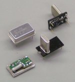
I "opened" some crystal oscillator modules last year in order to make a low jitter oscillator for my Sony CD transport, by using the components from these modules. First thing I noticed was the distance between the small decoupling cap and the oscillator chip, next, one connection of the crystal is routed all the way around, underneath the decoupling cap, to the oscillator chip (photograph bottom left). Then a very small crystal is used, similar size as the 32,768 KHz watch crystals.
What I did was using the oscillator chip from the existing module, and made some crystal oscillator modules (photo top right). Decoupling cap (4.7uF tantalium) is placed very close to the chip, the crystal is also placed close to the chip, using short connections. Everything is mounted on a single-sided PCB. The modules are pin compatible with the standard crystal module on the top left. This is something for DIY, the PCB is easy to make, and only a few components are needed. The chip (WF10192) can be removed from crystal modules found in obsolete computer equipment (main boards, video cards, networking cards and so on). The crystal modules have different chips / circuits inside, the 25 MHz KOYO KCO-120S modules have the WF10192 chip inside. To open the crystal module, firmly fixate it, use a small fine-tooth saw to cut all around the metal case, then gently pull off the top cover.
For the USBDI2S interface I needed 48 MHz, so I used a 16 MHz crystal on the third overtone, this required placing a low noise 2.4...2.7 K Ohm resistor in parallel with the crystal when using the WF10192.
Hi dddac,
Thanks for your reply [post #1362]
Crystal oscillator performance can be measured (to a certain extent) using a large bandwidth oscilloscope (x10 and maximum timebase setting). The transients should be clean and free of noise, you have to turn down beam intensity to minimum and make sure the beam focus setting is optimal. The thinnest and brightest transients are a indication for lowest jitter that can be measured this way. This is a course selection, next I test them in the DI 8M, the wider the stage and the higher the "resolution", the lower the (crystal) jitter.
But low jitter crystal oscillator is only a start, clock distribution / reclocking is extremely critical. Using good clock buffers and correct signal loading (reflections) are very important. Another very important thing is fine-tuning the clock buffer trigger window, this way the buffer can trigger on the portion of the clock transients that result in minimal phase noise. I now use a pull-up resistor (VCC) on the clock buffer input, this has significantly lowered phase noise.
During clock distribution, and loading with (multiple) loads, harmonics are "filtered" causing a non-ideal square wave shape (rounded edges or ringing).
The distorted clock waveform can cause additional noise / jitter. Reflected waves (due to incorrect signal loading) can add even more noise. I always use separate clock buffers for the DAC chips, and timing-chain.
The most important thing is lowest possible jitter measured directly on the DAC chip timing input (BCK or WS / LE).
I "opened" some crystal oscillator modules last year in order to make a low jitter oscillator for my Sony CD transport, by using the components from these modules. First thing I noticed was the distance between the small decoupling cap and the oscillator chip, next, one connection of the crystal is routed all the way around, underneath the decoupling cap, to the oscillator chip (photograph bottom left). Then a very small crystal is used, similar size as the 32,768 KHz watch crystals.
What I did was using the oscillator chip from the existing module, and made some crystal oscillator modules (photo top right). Decoupling cap (4.7uF tantalium) is placed very close to the chip, the crystal is also placed close to the chip, using short connections. Everything is mounted on a single-sided PCB. The modules are pin compatible with the standard crystal module on the top left. This is something for DIY, the PCB is easy to make, and only a few components are needed. The chip (WF10192) can be removed from crystal modules found in obsolete computer equipment (main boards, video cards, networking cards and so on). The crystal modules have different chips / circuits inside, the 25 MHz KOYO KCO-120S modules have the WF10192 chip inside. To open the crystal module, firmly fixate it, use a small fine-tooth saw to cut all around the metal case, then gently pull off the top cover.
For the USBDI2S interface I needed 48 MHz, so I used a 16 MHz crystal on the third overtone, this required placing a low noise 2.4...2.7 K Ohm resistor in parallel with the crystal when using the WF10192.
Attachments
Thanks for explaining the clock mod John.
You tweak every part of gear where you put your hands on, fascinating.
I opened a few big Xtals too last time, mostly they have a 74/04 as buffer, one had problably a PLL, i could not find any info of the used chip on www. Unfortunately i broke the ceramic pcb of it. Will search if i can scavenge more Xtals from the pile of pc hardware i have on the attic.
Hello,
Hopefully these questions weren't already asked...
Is BCLK the only signal reclocked in your USB-to-I2S board?
Also regarding your USB-to-I2S board, is the MCLK signal tapped from the PCM2706 in-phase with the WCLK signal? The digital filter of my DAC requires MCLK input, apparently to calculate the system clock multiplier.
Thanks,
Bryan
USB/DI2S I2S output signals
Hi bryman79,
Thanks for your reply [post #1367]
Yes, BCLK is the only signal reclocked in the USB/DI2S module.
Both DI 8 and DI 16 use BCK (2.8224 MHz) for timing, the chips used (TDA1543 and TDA1541A) output their samples on the first positive going edge of BCK after WS has gone low.
DI 8 / DI 16 Interpolation is achieved by using a digital delay unit, clocked by BCK, it latches the DAC chips sequentially, placing interpolated samples between the original samples, therefore no MCLK / SCLK is needed.
So MCLK / SCLK is not available from this module. However there is a 11.2896 MHz SCLK signal present on PCM2706 chip pin 18, but it has jitter. PCM2706 datasheet specifies it's internal DACs are running at 128*fs.
So there is no delay imparted to the BCLK signal by the reclocker? Or to put it another way, the reclocked BCLK signal is in-phase (i.e., remains in synchronization) with the MCLK signal from pin 18?
Thanks,
Bryan
Thanks,
Bryan
Hi bryman79,
Thanks for your reply [post #1369]
There is a delay caused by the reclocker. The maximum delay equals approx. 2x master clock (48MHz) period time, t=1/48,000,000=20.83ns, 2*20.83ns = 41.66ns.
This occurs when the BCK pulse goes high a fraction after the 48MHz master clock pulse goes high, then it will take a full 20.83ns delay to clock the first D flip-flop, and another 20.83ns to clock the second D flip-flop.
When used for driving a NOS DAC this is no problem as BCK period-time equals 35.4us. Both DATA and WS are sampled at half this period-time (17.7us), the maximum delay of 41.66ns stays well within this margin.
The USB/DI2S module is not capable of driving a OS DAC, without modifications.
Hi John
You use an LM4562 metal can for the I/V(and tube in mixed mode). Have you tested a / listened to THS4032? I placed it in the CD304mk2, really amazing. A lot better then the previous OPA2132, wich was to my taste some laid back mids/soundstage.
THS4032 can only be delivered in SOIC though, had to make an adapter for it. Soldered the SMD chip on a 8 pin dil socket, together with two 100 N Wima MKS ps caps to pin 3 wich is gnd in CD304.
Some LM4562's are planned to compare.
I/V OP-amp
Hi tubee,
thanks for your reply [post #1371]
I haven't tested the THS4032 yet, but I will give it a try. However I have my doubts about the relative high distortion of the THS4032 when compared to the 0.00003% of the LM4562 when driving a 600 Ohm load.
The THS4032 has much higher bandwidth (100MHz) compared to OPA2132 (8MHz), so it's no surprise it performs better than a OPA2132 in a I/V stage. It also depends on the application of course.
I used the same IC socket trick to test AD823 chips, last year.
Last week I almost blew-up my DI 8M prototype, I bought some TDA1541A chips from a Dutch supplier, turned out they were fake re-printed TDA1540 chips (mono 14 bit) with different connections. The font didn't match, and the circular shapes that are supposed to be shiny were mat, but I discovered that afterwards. Anyway it resulted in a massive short circuit (I replaced all 8 chips), causing a huge peak signal on my sonic resonators as well. Luckily both DI 8M and Sonic resonators survived.
The good news is, modding activities carried out this weekend dramatically improved DI 8M performance, again! The DI 8M now starts to put very high demands on my audio set.
John,
Can MCLK output from pin 18 of the PCM2706 be synchronized with DATA and BCLK via a f-f or other circuitry using the 48MHz clock? Clearly this would be on an external board, but it would at least allow me use it in my application.
Thanks,
Bryan
Can MCLK output from pin 18 of the PCM2706 be synchronized with DATA and BCLK via a f-f or other circuitry using the 48MHz clock? Clearly this would be on an external board, but it would at least allow me use it in my application.
Thanks,
Bryan
Hi John
Yes the distorsion of THS4032 is some higher, i can hear that. On the other hand; i love pop and sometimes Jazz, the THS gives a nice little "bite" 😀 on the music, it becomes more "involved", more live-like. But classical music (Mahlers vierter, recorded 1967!!) does sound good too. Last months i swapped a lot of opamps (OPA's AD's, LT's) the THS is so far winner. Use a relatively high impedance tube-pre amp as load for the THS.
Have the THS from another thread:
http://www.diyaudio.com/forums/showthread.php?postid=754215#post754215
Swapping the THS for an original NE5532 improves a lot (i replaced NE for opa2132 due laid back mids) but the NE5532 is in distorsion figures not that bad at all.
Haven't compared the THS with LM4562's yet.
They're different to 1541 for sure. I am right now looking at some TDA1540's am busy to look how to mod a CD300 😉
I understand why you don't want to tell the suppliers name, though i am really interested in it!
Yes the distorsion of THS4032 is some higher, i can hear that. On the other hand; i love pop and sometimes Jazz, the THS gives a nice little "bite" 😀 on the music, it becomes more "involved", more live-like. But classical music (Mahlers vierter, recorded 1967!!) does sound good too. Last months i swapped a lot of opamps (OPA's AD's, LT's) the THS is so far winner. Use a relatively high impedance tube-pre amp as load for the THS.
Have the THS from another thread:
http://www.diyaudio.com/forums/showthread.php?postid=754215#post754215
Swapping the THS for an original NE5532 improves a lot (i replaced NE for opa2132 due laid back mids) but the NE5532 is in distorsion figures not that bad at all.
Haven't compared the THS with LM4562's yet.
😱 😱 😱I bought some TDA1541A chips from a Dutch supplier, turned out they were fake re-printed TDA1540 chips (mono 14 bit) with different connections.
They're different to 1541 for sure. I am right now looking at some TDA1540's am busy to look how to mod a CD300 😉
I understand why you don't want to tell the suppliers name, though i am really interested in it!
It is not very obvious from this wich opamp i am currently using: it's the THS4032Swapping the THS for an original NE5532 improves a lot (i replaced NE for opa2132 due laid back mids) but the NE5532 is in distorsion figures not that bad at all.
Hi John
If i put the opamp in class A, can i use some other fet also besides the stated 2SK117? I am thinking pulling the THS in "A" with the 3rd one of your designs:
http://www.diyaudio.com/forums/attachment.php?s=&postid=1080950&stamp=1166033134
Hi John
Sorry for your time (and expertise 😀 ) want to add class a bias circuit on the THS double opamp. On wich stage shall i hook it, on pin 1 of first I/V stage, or on pin 7 of the buffer stage.
Thanks.
(Btw this thread is becoming also very nice for reviewing documents, schematics and techniques)
Sorry for your time (and expertise 😀 ) want to add class a bias circuit on the THS double opamp. On wich stage shall i hook it, on pin 1 of first I/V stage, or on pin 7 of the buffer stage.
Thanks.
(Btw this thread is becoming also very nice for reviewing documents, schematics and techniques)
USB/DI2S interface
Hi bryman79,
Thanks for your reply [post #1373]
sorry for the late reply, I have been working on both DI 8 (48/64 BCK) auto-detecting timing module and the universal I2S interface.
I will make a test setup this weekend, see if SCLK can be re-clocked, using the 48 MHz or higher frequency master clock.
However, you have to check your DAC specifications first, the PCM2706 outputs Philips format, BCK equals 64fs (PCM2706/PCM2707 datasheet page 19). As far as I can see, it can only provide 4X oversampling with this format (SCLK=11.2896, BCK=2.8224MHz).
I am also not sure if the FIR filter will still work correctly, using a re-clocked SCLK / MCLK.
OP-amps for I/V stage
Hi tubee,
Thanks for your reply [post #1374]
> Using the LM4562 enhances details significantly, sound is much clearer, and it doesn't sound laid-back at all like the OPA627.I also completely removed the (active) control amplifier. this increased sound quality significantly, the passive one (stepped resistor volume control) produces a much cleaner sound.
So now I basically drive the MOSFET power amplifier directly with the DI DAC, this is no problem as the DI DAC output amplitude can be adjusted by modifying the output attenuator. It will provide enough signal amplitude to drive virtually any power amplifier directly.
The sound produced by the DI 8(M) and DI 16(M) also sound very "involving". The reason for this I think is that they sound very clear (LM4562 low distortion), and the sound is in perfect "balance".
> At the time the THS4032 was discussed in the thread you indicated, the LM4562 wasn't released. So at that time the THS4032 would have probably been the best choice for a I/V stage. Because of the large bandwidth it probably sounded less laid-back as the OPA627 and would have had more detail.
> I can only suggest to give the LM4562 a try.
Re: USB/DI2S interface
I hope you can make it work. It would be a nice addition to your board, and add flexibility for integration with other designs.
The format should not be a problem for my application.
Thanks,
Bryan
-ecdesigns- said:I will make a test setup this weekend, see if SCLK can be re-clocked, using the 48 MHz or higher frequency master clock.]
I hope you can make it work. It would be a nice addition to your board, and add flexibility for integration with other designs.
Originally posted by -ecdesigns- However, you have to check your DAC specifications first, the PCM2706 outputs Philips format, BCK equals 64fs (PCM2706/PCM2707 datasheet page 19). As far as I can see, it can only provide 4X oversampling with this format (SCLK=11.2896, BCK=2.8224MHz).
The format should not be a problem for my application.
Thanks,
Bryan
volume control on DI 8
Hi EC, I've been away for awhile but I'm happy to see you have added volume control on the DI 8. I think preamps usually color the sound of CDP. Is the volume remote controlled? I'm going to triamp my speakers in the future. Would it be possible for the DI 8 to have 3 sets of analogue outputs for triamping? Thanks.
Hi EC, I've been away for awhile but I'm happy to see you have added volume control on the DI 8. I think preamps usually color the sound of CDP. Is the volume remote controlled? I'm going to triamp my speakers in the future. Would it be possible for the DI 8 to have 3 sets of analogue outputs for triamping? Thanks.
- Home
- Source & Line
- Digital Line Level
- Building the ultimate NOS DAC using TDA1541A