Ecdesigns wrote:
Have a philips '86 plastic cdp modded to a non-os test player. I2S to 1541A, kwak clock 7, rbroertjes transistor I/V with sanken transistors. After listening tests i removed the 3rd order Bessel before I/V, didn't like the sound. Without its more live-like or real.
So what can we do to improve the D-I DAC or NOS-DAC? just add a phaselinear filter (Bessel) that filters out most of the unwanted harmonics (see FFT analysis). In this way we can still preserve phase linearity ensuring realistic sound reproduction.
Have a philips '86 plastic cdp modded to a non-os test player. I2S to 1541A, kwak clock 7, rbroertjes transistor I/V with sanken transistors. After listening tests i removed the 3rd order Bessel before I/V, didn't like the sound. Without its more live-like or real.
What does interest me, is if the linear interpolation creates measurable errors with 1k sine 0dB and -60dB.
Above 5k IMHO it doesn't matter because for example for 5k the healthy K2 is already 10k and K3 = 15K and shouldn't hurt anymore.
Above 5k IMHO it doesn't matter because for example for 5k the healthy K2 is already 10k and K3 = 15K and shouldn't hurt anymore.
Overview
Hi dddac,
Thanks for your replay,
1) No the reference DAC uses one single TDA1541A, no filter
2) The D-I DAC uses 2, 4 or 8 DAC's to create a differential output signal to eliminate DC offset and cancel-out interference, produces a smoother signal, reduce linearity errors, makes filtering easier and increases dynamics. More DAC's > smoother signal > easier filtering> less linearity errors > increased dynamics.
3) The twin-DAC mentioned earlier (my old DAC) uses 2 DAC's to create a differential output signal to eliminate DC offset and cancel-out interference,
that is fed to a differential amplifier, this is then fed into a 8th order filter to suppress higher harmonics.
The output of the D-I DAC can be filtered more easily and phase linear Bessel filters can be used for this purpose.
If you want to filter out these harmonics with the course step signal (paralleled DAC's), you would filter out detail in the process and cause phase linearity errors.
1 KHz sinewave
Hi Bernhard,
Thanks for your reply,
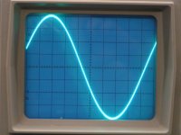
The 1 KHz sinewave looks perfect on the oscilloscope, FFT shows only 1 peak. The sound is very realistic and clear. Measurements show that linear interpolation creates triangle shaped waves (but only at higher frequencies that have few samples, these become clearly visible) they contain mainly even harmonics, just like tube amplifiers. So in my opinion the linear interpolation error isn't affecting the signal in a negative way. The squarewave that is comming from a standard NOS-DAC at higher frequencies mainly contain odd harmonics, these do not sound nice
Hi Bernhard,
Thanks for your reply,
The 1 KHz sinewave looks perfect on the oscilloscope, FFT shows only 1 peak. The sound is very realistic and clear. Measurements show that linear interpolation creates triangle shaped waves (but only at higher frequencies that have few samples, these become clearly visible) they contain mainly even harmonics, just like tube amplifiers. So in my opinion the linear interpolation error isn't affecting the signal in a negative way. The squarewave that is comming from a standard NOS-DAC at higher frequencies mainly contain odd harmonics, these do not sound nice
Hi, tubee
thanks for your reply,
That is an interesting point, measurements show that you must "correct" the imperfect signal because theoretically it shouldn't look like that, but doing so affects sound quality in a positive or a negative way. Some people like the filtered sound, some people don't. That is exactly why I started designing a NON-oversampling DAC with smoother steps so I could leave-out the filter, but without covering-up detail (squarewaves, FFT example NOS-DAC). The result is the D-I DAC.
Perhaps a bypassable, well designed Bessel filter (just in case) is a good alternative. Or a separate filter module.
Re: 1 KHz sinewave
How far can you look down ? Which signal ? Normal CD player should be clean to > -90 dB
-ecdesigns- said:FFT shows only 1 peak.
How far can you look down ? Which signal ? Normal CD player should be clean to > -90 dB
Hi Bernhard,
Thanks for your reply,
The range covered is dc to 25KHz, when a 1 KHz sinewave is used, I see the fundamental 1KHz plus a weaker harmonic. With some other frequencies I even get more harmonics. If it was the recording, it should show with the other DAC's too I think. Perhaps it is caused by bad post filtering.
I have done some comparing between the octal D-I DAC I "assembled" today and the other NOS-DAC's (reference DAC and the filtered NOS-DAC). I also tried filters on the octal D-I DAC.
I just started listening, then the sound was gone and a loud hissing noise appeared. Then I remembered, forgot to buffer BCK (there are a lot of chips connected to it, 23 in total). After I installed a non-inverting buffer on BCLK, everything worked fine.
The first impressions are:
The D-I DAC has more detail then the NOS-DAC and the NOS-DAC with 8th order filter. It's midrange is fuller, warmer, the sound is more open, more natural. It sounds like a filterless NOS-DAC with the detail I was already used to from the NOS-DAC with 8th order filter.
When I added the 8th order filter it sounded more like the NOS-DAC with 8th order filter. So basically the D-I DAC seems to sound best with no filtering at all, just the direct diff-amp output. The unfiltered output signal ,contains a very weak 352.8 KHz residu. But my set has no problem with that as the MOSFET cascode power amplifier's bandwith is only approx. 200KHz. On the oscilloscope you can no longer see any steps in the output signal, only with high frequencies with very few samples, you see the samples "connected" by a straight line.
non-linear interpolation / summary
Hi, all
I have been thinking of how to apply non-linear interpolation to reduce errors. Basically each DAC group represents a bit (binary system), so theoretically an octal D-I DAC has 3 bits added (19 bits in total).
DAC1: D2 = "0"
DAC1+DAC2: D2 = "1"
DAC3: D1 = "0"
DAC3+DAC4: D1 = "1"
DAC5+DAC6: D0 = "0"
DAC5+DAC6+DAC7+DAC8: D0 = "1"
Now if we could get the following voltage steps from this binary coded signal, the interpolation would be non-linear and the straight lines between samples would be curved, to resemble the shape of a sinewave instead of triangle shaped and thereby reducing the errors of linear interpolation for high frequencies in particular.
0 0 0 > 0 deg. 0
0 0 1 > 11.25 deg. > 0.195
0 1 0 > 22.5 deg. > 0.382
0 1 1 > 33.75 deg. > 0.555
1 0 0 > 45 deg. > 0.707
1 0 1 > 56.25 deg. > 0.831
1 1 0 > 67.5 deg. > 0.92
1 1 1 > 90 deg. > 1
The two systems both Linear and non-linear can then be compared to see if it improves the sound.
Other alternative is a mixture of Linear and non-linear interpolation, D2: non linear, D1 and D0 linear (simplifies design).
How to implement this in the existing D-I DAC? by adding more I/V converters and the use of summing resistors with different values, or, with a passive I/V converter, it's basically the same: different resistor values of the summing resistors and a separate I/V conversion resistor at eac DAC group, this also has the benefit of reducing the voltage drop across te individual I/V resistors.
I have already tried to implement this by varying sample size (easiest way) but the result was a relatively high distortion.
For those who are afraid this interpolation concept affects the pure, clear NOS-DAC sound, Remember I keep comparing the D-I DAC with the reference NOS-DAC all the time wit both measurements and listening sessions using test CD's.
SUMMARY:
The D-I DAC uses 2, 4 or 8 DAC's. The TDA1541A DAC module is ready post #9
The Timing chain module (basically a digital delay line) increases resolution by creating shorter samples (8BCK with the octal D-I DAC) and more steps. It is designed to drive 2,4 and 8 DAC's. This module is ready post #41, #77, #78
The I/V stages and differential amplifier module (under development) post # 50
The D-I DAC still has the properties of a NOS-DAC and runs on 44.1KHz post #100
Main advantage of the D-I DAC is a smooth unfiltered output signal post #64
The D-I DAC works with both, OP-amp and tube output stages
The D-I DAC can be used with both active and passive I/V converters
The D-I DAC concept can also be implemented with DAC chips other than the TDA 1541A, but the DAC chips must support I2S and should have no internal filter. Or the internal filter must be bypassable.
The octal D-I DAC basically needs no filtering at all: direct output of diff-amp or tube output stage post #100
Re: non-linear interpolation / summary
PCBs?
-ecdesigns- said:
SUMMARY:
The D-I DAC uses 2, 4 or 8 DAC's. The TDA1541A DAC module is ready post #9
The Timing chain module (basically a digital delay line) increases resolution by creating shorter samples (8BCK with the octal D-I DAC) and more steps. It is designed to drive 2,4 and 8 DAC's. This module is ready post #41, #77, #78
PCBs?
Re: non-linear interpolation / summary
This is good if the input is a sine wave. What would be the effect on a square wave?
-ecdesigns- said:Hi, all
I have been thinking of how to apply non-linear interpolation to reduce errors. Basically each DAC group represents a bit (binary system), so theoretically an octal D-I DAC has 3 bits added (19 bits in total).
DAC1: D2 = "0"
DAC1+DAC2: D2 = "1"
DAC3: D1 = "0"
DAC3+DAC4: D1 = "1"
DAC5+DAC6: D0 = "0"
DAC5+DAC6+DAC7+DAC8: D0 = "1"
Now if we could get the following voltage steps from this binary coded signal, the interpolation would be non-linear and the straight lines between samples would be curved, to resemble the shape of a sinewave instead of triangle shaped and thereby reducing the errors of linear interpolation for high frequencies in particular.
0 0 0 > 0 deg. 0
0 0 1 > 11.25 deg. > 0.195
0 1 0 > 22.5 deg. > 0.382
0 1 1 > 33.75 deg. > 0.555
1 0 0 > 45 deg. > 0.707
1 0 1 > 56.25 deg. > 0.831
1 1 0 > 67.5 deg. > 0.92
1 1 1 > 90 deg. > 1
The two systems both Linear and non-linear can then be compared to see if it improves the sound.
Other alternative is a mixture of Linear and non-linear interpolation, D2: non linear, D1 and D0 linear (simplifies design).
This is good if the input is a sine wave. What would be the effect on a square wave?
-ecdesigns-, would not this calculation hold only for 1/4 of 11kHz sine wave with sample at 0 degrees? But I may have missed something.
Re: non-linear interpolation / summary
1. Curve fitting algorithms already exist. Have done for a century or two.
2. How do you plan to relate the degree of curvature to frequency of the waveform ?
-ecdesigns- said:Now if we could get the following voltage steps from this binary coded signal, the interpolation would be non-linear and the straight lines between samples would be curved, to resemble the shape of a sinewave instead of triangle shaped and thereby reducing the errors of linear interpolation for high frequencies in particular.
1. Curve fitting algorithms already exist. Have done for a century or two.
2. How do you plan to relate the degree of curvature to frequency of the waveform ?
Ecdesigsn: there's a lot to do with a 1541 chip. I reclocked the Masterclock after Kwak 7 with a /4 divider to the dac. (With OS, with 7220 it has to be /2) This enhances sound quality again. How is the clock signal fed to the dacs in the D-I dac? Even if the signal of clock look good on the scope, it might profit from reclocking and/or dividing too.
octal D-I DAC
Hi, all
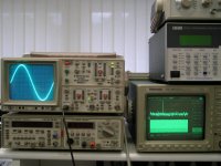
I have some pictures of the octal D-I dac output signal at 2, 6 and 8 KHz + FFT and a photo of the octal D-I DAC prototype.
>Squarewaves with infinite risetimes in your output signal means very high frequency harmonics, the highest frequency from a 44.1KHz sampled signal would be around 20 KHz. So a perfect D/A conversion should never show a sinewave frequency much higher than that. The risetime of a squarewave must be accordingly. If your DAC outputs a perfect (infinit risetime) squarewave at say 5 KHz, you have added some higher harmonics to the audio signal that don't belong there. With a good functioning DAC you would see a trapezium shaped squarewave at this frequency, there should be hardly any "ringing" on the edges.
>The D-I DAC output signal shape is dominated by DAC-1, So this basic shape stays. DAC's 2...7 only add steps between the steps of DAC1, but always within the DAC1 envelope. Even with linear interpolation the error stays within limits.
>The waveshaping I was talking about mainly affects higher frequencies (above around 10KHz as the amount of samples is greatly reduced. Without linear interpolation you would get a squarewave instead of a triangle shape. As I mentioned before I'm not sure if this would be audible.
The added oscillogram shows a 2000Hz sinewave, the output is unfiltered!
Hi, all
I have some pictures of the octal D-I dac output signal at 2, 6 and 8 KHz + FFT and a photo of the octal D-I DAC prototype.
>Squarewaves with infinite risetimes in your output signal means very high frequency harmonics, the highest frequency from a 44.1KHz sampled signal would be around 20 KHz. So a perfect D/A conversion should never show a sinewave frequency much higher than that. The risetime of a squarewave must be accordingly. If your DAC outputs a perfect (infinit risetime) squarewave at say 5 KHz, you have added some higher harmonics to the audio signal that don't belong there. With a good functioning DAC you would see a trapezium shaped squarewave at this frequency, there should be hardly any "ringing" on the edges.
>The D-I DAC output signal shape is dominated by DAC-1, So this basic shape stays. DAC's 2...7 only add steps between the steps of DAC1, but always within the DAC1 envelope. Even with linear interpolation the error stays within limits.
>The waveshaping I was talking about mainly affects higher frequencies (above around 10KHz as the amount of samples is greatly reduced. Without linear interpolation you would get a squarewave instead of a triangle shape. As I mentioned before I'm not sure if this would be audible.
The added oscillogram shows a 2000Hz sinewave, the output is unfiltered!
Attachments
ec,
A 5 kHz square wave should not look like a trapezoid... rather it should appear exactly as a 5 khz sine with 15 kHz sine at 1/3 the magnitude superimposed upon it.
It is because of this, that squarewave testing, and the results thereof must be considered very carefully when analysing amplifiers etc... squarewave analysis lends itself to gross misinterpretation by those that don't know (or choose to ignore) the Fourier stuff behind it all.
In the case of a DAC with a brickwall, or a properly oversampled signal, the harmonics which create the "corners" of a trapezoid simply should not be there.
- Home
- Source & Line
- Digital Line Level
- Building the ultimate NOS DAC using TDA1541A