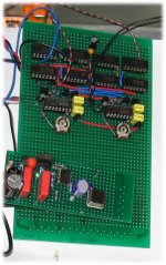
DI16 core PCB:
It's alive! It's alive! 😀 😀
Finally, he saw the light this morning.
I can't speak much about the sound because I'm using the crappy system of my job's PC 🙁 ...and I'm stuck here 'till tomorrow...
I only can say that it sounds verrry detailed and smooth. Bass is beginning to open.
Tomorrow I'll connect it to my big system and we'll see...
I had "a little complication" that delayed the birth. I used a PS from another project for the digital section and it did not cope with the task. Today I made a stronger one but it's 13V. The regs are a little hot. Maybe I'll add a "gyrator" to waste some heat 😀 and clean it further...
Mmmh, DC offset is 10mV and 80mV. I will have to permutate the chips. Any advice will be appreciated.
Many, many thanks to John for his epic effort
Cheers,
M
Very rational design
As been pointed by others, there might be shortcomings in the digital "filtering"implementation by ecdesigns(John) , the main issue is that with this direct interpolation technique, the impulse response will not be like what it should, for example the 22 Khz sine (square 😀 ) will end later than it should, since the DAC is clocked in progression, so the last dac present it's output later than other DACs
however as John progresses, and do many experiment, it seems that this approach in fact can sound good, and he didn't report anomalies in sound reproduction / listening session.
I have an assumption why is this so. The fact that the dac output it's data in progression can be likened to speaker line arrays. The closest speaker to the listener will be heard first and the furthest one last. There are disadvantage to line array, but in many situation the Line array advantages far outweight it's disadvantages.
And in this case is even less so because the delay in clocking is very tiny, even tweeter to enclosure [multiple] reflection will contribute much more than that.
This doesn't mean that it's not audible (at least it's measurable 😉 ) , but in fact very rational trade off, considering it's advantages:reduction of higher order harmonics, and lower signal to noise ratio from paralleling.
😀 😀 😀 Nice work !! 😀 😀 😀
Hi maxlorenz,
I assume you were in quite a hurry to assemble the DI 16. You managed to get it assembled an running in only a few days? My congratulations, good work!
What digital sound source did you use, and how did you connect it to the DI 16 core?
The detailed sound is typical for D-I DACs, everything recorded on a CD(image) get's trough, even very small sample-to sample changes.
The smooth sound is a result of approx. 256x resolution enhancement.
> The voltage regulators need cooling, this is noted in the assembly instructions. I placed them at the edge of the PCB, so they can be mounted to a heatsink. Each voltage regulator needs to be mounted to this heatsink using an insulation set. 13V power supply for U36...U38 is no problem.
> The DC offset is a result of random placement of the TDA1543 chips that have different tolerances. This needs some tuning, the DI 16 has two DAC groups, the non-inverting DAC group (U17...24), and the inverting DAC group (U25...U32).
Now by swapping TDA1543 chips between these two groups and measuring the DC offset after each swap, it's possible to obtain very low DC offsets for both channels.
There is a slight difference between L and R channel DC offset, if this can't be fully eliminated by swapping chips between both DAC groups, try to obtain lowest DC offset first. Then use a simple bias circuit to feed a corrective bias current into one I/V stage of each channel. The small DC offset voltages (1...3mV) can now be trimmed to a few hundred microvolts or less.
If you are using the LM4562, sound quality can be significantly improved by using an external "class A" bias current circuit. This external bias current causes a slight bias increase in the LM4562 output stage, and may improve negative feedback loop stability.
To get an impression of what's possible, connect a 18 K Ohm resistor between the LM4562 output and -15V. The LM4562 "thin" sound will disappear completely, and sound will be much more refined. The best bias circuit I tested so far is the cascode bias circuit using 2 JFETs, set at 1mA bias current.
Hi Ecdesigns 🙂
Thank you for the compliments. As I've confessed, I am an obsessive-compulsive DIYer 😀 When I see a good project I can't wait to build it. Imagine if I actually knew what I was doing... he,he...
For now, only PC. I use Doede's USB/I2S module, wich is easy to build, realiable, sounds good and is "bon marché" 😉
I use for now solid core 20AWG silver cable (homegrownaudio.com). Short signal path, braided leads. Yes, I remember all your advices about shielding/isolating BCK...I could shield the signal cables but it won't look nice...heavy shield.
Even on these low quality speakers the character that you comment is apparent. There is a feel of "continuity" and "flow" on the music.
Of course, I use TO220 type heatsinks but I have to build/buy bigger ones.
I must have measured wrongly; now it is 8.9mV v/s 2.6mV, during playback...
...it's easy for you to say so...😀
I remember that tip.
I have here some J511 CRD's, wich gives +/-4mA. Is it too much?
Or are they noisy?
The J506 is 1.3mA...
You do mean from each output to -15V, right?
I installed a "gyrator" on the digital supply, consistent in a BDX33C Darlington with 6.8uF (Wima MKS4) + 18K as filter (the only one I've tried) . The voltage went down too much, until 8V. I tried it, nevertheless, and it doesn't sound bad: highs seem a little restricted (less "air") but all the previous merits are there, plus it sound more authoritative and weighty, as always that I try this mod (like a BIG Wima). I'll wait for burn-in.
I don't know if the 7806 regs are comfortable with only 2V above 🙁
Allow me to abuse: do I have to increase R from collector to base on my gyrator?
Thanks for your interest and help.
M
I assume you were in quite a hurry to assemble the DI 16. You managed to get it assembled an running in only a few days? My congratulations, good work!
Thank you for the compliments. As I've confessed, I am an obsessive-compulsive DIYer 😀 When I see a good project I can't wait to build it. Imagine if I actually knew what I was doing... he,he...
What digital sound source did you use, and how did you connect it to the DI 16 core?
For now, only PC. I use Doede's USB/I2S module, wich is easy to build, realiable, sounds good and is "bon marché" 😉
I use for now solid core 20AWG silver cable (homegrownaudio.com). Short signal path, braided leads. Yes, I remember all your advices about shielding/isolating BCK...I could shield the signal cables but it won't look nice...heavy shield.
The detailed sound is typical for D-I DACs, everything recorded on a CD(image) get's trough, even very small sample-to sample changes. The smooth sound is a result of approx. 256x resolution enhancement.
Even on these low quality speakers the character that you comment is apparent. There is a feel of "continuity" and "flow" on the music.
> The voltage regulators need cooling, this is noted in the assembly instructions.
Of course, I use TO220 type heatsinks but I have to build/buy bigger ones.
> The DC offset is a result of random placement of the TDA1543 chips that have different tolerances.
I must have measured wrongly; now it is 8.9mV v/s 2.6mV, during playback...
...Then use a simple bias circuit to feed a corrective bias current into one I/V stage of each channel...
...it's easy for you to say so...😀
I remember that tip.
If you are using the LM4562, sound quality can be significantly improved by using an external "class A" bias current circuit.
I have here some J511 CRD's, wich gives +/-4mA. Is it too much?
Or are they noisy?
The J506 is 1.3mA...
You do mean from each output to -15V, right?
I installed a "gyrator" on the digital supply, consistent in a BDX33C Darlington with 6.8uF (Wima MKS4) + 18K as filter (the only one I've tried) . The voltage went down too much, until 8V. I tried it, nevertheless, and it doesn't sound bad: highs seem a little restricted (less "air") but all the previous merits are there, plus it sound more authoritative and weighty, as always that I try this mod (like a BIG Wima). I'll wait for burn-in.
I don't know if the 7806 regs are comfortable with only 2V above 🙁
Allow me to abuse: do I have to increase R from collector to base on my gyrator?
Thanks for your interest and help.
M
Hi
thanks again for the good thread going on...
*
I have 2 Q about passive Riv
*
"With the PCM56, the passive I/V works very good up to > 500 ohms."
what about values of less then 500 ohm?
like 200 ohm for the example, is the distorsions maybe higher or what?
*
which low value of Riv (the lowest) I can use for the TDA1543 but not to burn the chip, and keep the distorsion at low level?
Is there any correlation between Riv and Rv_ref?
Now I am using the values of 1350 ohm for Rv_ref and 2.2K per unit (16 TDA1543 in parallel)
*
thanks
BTW
it is from vital importance to have larger heatsinks when operate in parallel, and from higher (8V to 8.5V) power suply voltages...
*
with just slightly warm DACs heatsink You will expect no differents in L/R,
inkreasing the upper bandwith, and huge improvement of sound image,
which is not case when chips are overheated...
*
I have to design special heatsinks, bigger one (for use without fan)
this was from the personal experiance...
I did not measure the temperature of the heatsink in operation but as I can tell,
that is just little higher then body temperature...
thanks
Re: Very rational design
The Line array theory is a sort of used also by someone else to depict in a simple way the problems what can occur when digital OS is used. He explained that each time the signal is oversampled, a new point source is created, but then shifted in time from the original. Nonos has only one source then. Can't find the site again.
Maxlorentz: The gyrator works perfect! I tried the "flea" in p2p with a Tent XO, very good, and can put my own diy XO in it too. 😀
Hartono said:As been pointed by others, there might be shortcomings in the digital "filtering"implementation by ecdesigns(John) , the main issue is that with this direct interpolation technique, the impulse response will not be like what it should, for example the 22 Khz sine (square 😀 ) will end later than it should, since the DAC is clocked in progression, so the last dac present it's output later than other DACs
however as John progresses, and do many experiment, it seems that this approach in fact can sound good, and he didn't report anomalies in sound reproduction / listening session.
I have an assumption why is this so. The fact that the dac output it's data in progression can be likened to speaker line arrays. The closest speaker to the listener will be heard first and the furthest one last. There are disadvantage to line array, but in many situation the Line array advantages far outweight it's disadvantages.
😀 😀 😀 Nice work !! 😀 😀 😀
The Line array theory is a sort of used also by someone else to depict in a simple way the problems what can occur when digital OS is used. He explained that each time the signal is oversampled, a new point source is created, but then shifted in time from the original. Nonos has only one source then. Can't find the site again.
Maxlorentz: The gyrator works perfect! I tried the "flea" in p2p with a Tent XO, very good, and can put my own diy XO in it too. 😀
Attachments
Zoran said:Hi
"With the PCM56, the passive I/V works very good up to > 500 ohms."
what about values of less then 500 ohm?
like 200 ohm for the example, is the distorsions maybe higher or what?
/B]
Hi Zoran. triodedick advises 100 Ohm: http://www.diyaudio.com/forums/showthread.php?postid=1204665#post1204665
Zoran said:what about values of less then 500 ohm?
like 200 ohm for the example, is the distorsions maybe higher or what?
Less is better in theory, but with 1khz 0dB signal, 500ohm doesn't show any harmonics down to -90 dB.
Hi Tubee,
Yes the gyrator is a good discovery. In my limited experience the quality of the passive parts is relevant: I used Wima or Epcos polyester caps and they do sound slightly different, at least at first. Epcos being more neutral and Wima being more colorful.
Am I crazy?
I can't say that I understand the circuit completelly
To waste less voltage, should I increase R?
Cheers,
M
Box collector 😉
maxlorenz said:Hi Tubee,
Yes the gyrator is a good discovery. In my limited experience the quality of the passive parts is relevant: I used Wima or Epcos polyester caps and they do sound slightly different, at least at first. Epcos being more neutral and Wima being more colorful.
Am I crazy?
I can't say that I understand the circuit completelly
To waste less voltage, should I increase R?
Cheers,
M
Box collector 😉
Hi "box collector" M:
I only altered the PS for a Tent XO once (LM78** based PS to TL431 shunt based PS): a huge difference in sound was the result. Every part has it's influence, make of cap too. Epcos has a good name indeed.
Bernhard said:
Less is better in theory, but with 1khz 0dB signal, 500ohm doesn't show any harmonics down to -90 dB.
I go for -120dB, at least 😉
tubee said:
I go for -120dB, at least 😉
But not with a 16bit DAC 😉
-94dB is the limitation of my analyzer.


tubee said:
I go for -120dB, at least 😉
What amplifiers and speakers do you use to take any advantage of this ??
 .....
..... Bernhard said:
But not with a 16bit DAC 😉
-94dB is the limitation of my analyzer.
To get the lowest noise floor as possible is best for all sakes imo.
dddac said:
What amplifiers and speakers do you use to take any advantage of this ??
Regular stuff: tubed pre, hybrid (tube/fet) amp, TQWT 2 way speakers, all diy and selected in time. Still: lowest noise floor is best to get full advantage of dynamic range.
tubee said:Still: lowest noise floor is best to get full advantage of dynamic range.
Remember:
The low level distortion in multibit DACs is your second worst enemy*.
If I had the choice between the noise and the distortion I would go for the noise.
😀
😀
😀
😀
😀
😀
😀
* Your worst enemy is oversampling.
TDA1543 Riv...
which low value of Riv (the lowest) I can use for the TDA1543 but not to burn the chip, and keep the distorsion at low level?
Is there any correlation between Riv and Rv_ref?
Now I am using the values of 1350 ohm for Rv_ref and about 2.2K per unit (16 TDA1543 in parallel)
thanks
which low value of Riv (the lowest) I can use for the TDA1543 but not to burn the chip, and keep the distorsion at low level?
Is there any correlation between Riv and Rv_ref?
Now I am using the values of 1350 ohm for Rv_ref and about 2.2K per unit (16 TDA1543 in parallel)
thanks
Hi Zoran,
Thanks for your reply [post#1438]
You can't burn-up the chip using too low Riv, because the full scale current of each DAC chip is limited to 2.3mA, so with 16 DAC chips in parallel, full scale current is only 36.8mA. All that will happen is that the ac output voltage will drop when Riv value get's lower.
RiV sets the signal amplitude (gain). Riv = Vout / i(full scale) * number of DAC chips in parallel
The TDA1543 full scale current equals 2.3 mA or 0.0023 A
Example you want 2.8Vpp output voltage (1Vrms):
Riv = 2.8 / (0.0023 * 16) = 76 Ohm
You can pick 82 Ohm from the E12 range. The output voltage will now be slightly higher.
Rv_ref sets the DC offset voltage, usually this needs to be approx. half the power supply voltage. This is necessary to make optimal use of the available power supply voltage (max. 8V). The DC offset voltage can be fine-tuned for minimal distortion.
So calculate Riv first, mount the closest value from the E12 range
Use a 1 KHz 0dB sinewave signal (test CD or wav file). Now temporarily use a potentiometer for Rv_ref (approx. 250 Ohms for 16 DAC chips) and adjust for minimum distortion / 4V DC level (at 8V power supply voltage). Next measure the exact value of the potentiometer after the adjustment, and mount a resistor of approx. the same value from the E12 range.
Instead of using a resistor (Rv_ref), it's also possible to use a constant current source instead. This will prevent ground noise being dumped on the Vref input (and on the internal current reference source). Any HF interference on the Vref pin(s) will find it's way to the DAC outputs.
When connecting multiple Vref pins directly together, while there is the slightest voltage drop between the TDA1543 chips, crosstalk between the DAC chips will occur, this could result in a muddy sound as the internal current reference sources no longer provide a clean output current. An easy solution is to use a separate Rv_ref resistor for each chip, and solder it directly to the TDA1543 GND pin. The value of each separate Rv_ref resistor is the measured value (potentiometer) multiplied by the number of DAC chips.
Riv should be a single low noise resistor, if you use multiple resistors here, crosstalk will occur (voltage drop between the 16 DAC chips).
Best power supply scheme is to route all TDA1543 GND pins to star ground, this avoids crosstalk between the chips. Connect Riv also to this star ground.
Do realize that this circuit no longer guarantees the typical 0.018% distortion as noted in the TDA1543 datasheet. This low distortion value only applies when 25mV ac output compliance is met (TDA1543 datasheet page 7, analog outputs). The passive I/V circuit violates this 25mv compliance significantly, needless to say this is going to increase distortion quite a bit.
The produced distortion could sound nice, as it's likely to be even harmonic distortion. I personally try to avoid distortion whenever possible.
The passive I/V distortion can be significantly reduced by using a OP-amp I/V converter, using the new LM4562, and force it into class A mode by connecting a 18 K Ohm resistor between the output and -15V, this will stabilize the negative feedback loop. When using this circuit, all TDA1543 chips can run on 5...6V.
Even better is to use a balanced design, then the design can be fully DC coupled, eliminating sound coloring from the coupling capacitor.
Hi maxlorenz,
Thanks for your reply [post #1425]
The USB interface from DDAC probably uses a PCM2707 without jitter correction, basically the standard TI application. I measured very high jitter with such applications, up to 1000ps!
By using the relatively simple shiftregister reclocker (48 MHz crystal and some shift registers), the jitter frequency components that degrade sound quality can be reduced to approx. 50...100 pS, this makes a HUGE difference. It's also possible to just use the USBDI2S PCB.
I used small diameter (3 mm diameter) shielded cable for both BCK and DATA.
You need to measure DC offset voltage with no signal applied, otherwise the measurement is incorrect.
If I am correct, the J500 series current regulators have just been discontinued (RoHS?), so now it seems we have to use the discrete cascode bias circuit.
1.3 mA is a bit high, the trick is to use just enough bias current to obtain optimal performance.
I experimented with bias current in discrete all JFET OP-amp circuits, the external bias doesn't have the same effect as directly increasing the OP-amp's bias current. The external bias current seems to stabilize the OP-amp's feedback loop, significantly decreasing distortion.
Yes, a current source (or 18 K Ohm resistor) has to be connected between each of the 6 LM4562 outputs and -15V.
2V voltage drop for the 7806 is probably just not enough. Use at least 4...5V, especially when a ripple voltage is present on the input voltage (check this with the multimeter in AC position).
The base collector resistor value depends on the HFE of the transistor used. Transistors with lower HFE need more base current, so the collector-basis resistor value needs to be lower, this can be compensated by increasing the capacitor value between base and GND.
- Home
- Source & Line
- Digital Line Level
- Building the ultimate NOS DAC using TDA1541A