Hi maxlorenz,
Thanks for your comments on the DI 16.
Long audio interlinks are not recommended, I presently use 40 cm interlinks, it's better to use 5m USB interlink, or add a USB extension cable with repeater to the 5m USB interlink. However this depends on the USB audio interface specifications.
I had a look at the first DDDAC USB interface, it looks like a standard PCM2707 application without reclocker. The low jitter crystal oscillator is used to provide the 12 MHz clock signal for the PCM2707. This is basically little effective, as this clock is merely used for USB communications. The "low jitter" clock is derived from a SpAct PLL circuit that still adds up to 1000ps jitter, despite the low jitter crystal.
The USB/DI2S module shiftregister reclocker removes all jitter frequency components that degrade sound quality, regardless of the input jitter. It can handle clock jitter from the PCM2706 of up to 10000ps! The design is highly optimized (each chip has a separate power supply filter), the 48 MHz low jitter master clock drives both the PCM2606 and the shiftregister reclocker. The USB/DI2S module also provides extensive PCM2606 output bufferering (RS422 transceivers). The result is a sound quality that's virtually identical to the direct low jitter I2S output of very high quality CD transports.
With the USB/DI2S module, PC "quality" isn't an issue, as long as it has enough processing power left to maintain correct isochronous communications with the USB audio interface chip, and doesn't make too much noise. The old 500 MHz iMac I used for testing works very well and it's whisper silent as it has convection cooling.
The D-I system manages to increase resolution (removes edginess) without changing the original sample values.
This is the effect increasing time resolution (352.8KHz / 705.6 KHz), removing non-linearities from the system, and leaving out the analog output filter. Now there is almost nothing "tampering" with the music signal, optimal phase resolution / linearity is obtained.
I am not talking about phase shifts between a 20 KHz test sinewave signal and the signal generated by the DAC. I am referring to the minute phase shifts that occur with complex music signals. These translate in minute sample-to sample fluctuations (as time resolution is very limited due to 44.1 KHz sample rate). OS DACs will remove these fluctuations by averaging between many samples / brickwall filtering, basically limiting phase resolution. This results in removal of spatial information, resulting in a dull "flat" sound.
NOS DACs can retrieve (part of) these small sample-to sample fluctuations, and therefore produce a more spatial (natural) sound that's no longer dull or "flat". However NOS DACs need some form of filtering to remove (part of) the edginess caused by the course (time) resolution, this will remove / distort some of the spatial information.
The DI 16 "relaxed" sound quality is probably caused by the long RCA interlinks (5 meters) and the USB interface jitter. I am pretty sure that by using short interlinks and a low jitter USB interface, sound quality can be significantly improved.
During experiments that had the aim to reduce the "gap" in sound quality between the DI 16 and the DI 8(M), it became clear that DI 16 sound quality can be significantly improved.
First I converted the DI 16 into a DI 8 by only using TDA1543 chips with reference numbers U17, U19, U21, U23, U25, U27, U29 and U31 on the DI 16C core. This was done to increase interpolation filter bandwidth.
In order to achieve the same output voltage, I placed the removed chips in parallel with the remaining TDA1543 chips.
The difference between DI 16 and DI 8 sound quality was now significantly reduced, but still clearly audible.
Then I placed 3 x TDA1543 in parallel (24 x TDA1543 in total), I had to adapt the output attenuator, now it was quite difficult to tell the difference with the DI 8. It was only audible by direct comparison.
Thanks for your comments on the DI 16.
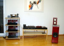
2) My beloved one wouldn't let me put the PC on the listening room (5*6.7*2.7m)... who would blame her...so the PC is located on the next room, signal driven through 5m interconnects! (common type balanced, shielded, mic cable).
Long audio interlinks are not recommended, I presently use 40 cm interlinks, it's better to use 5m USB interlink, or add a USB extension cable with repeater to the 5m USB interlink. However this depends on the USB audio interface specifications.
I had a look at the first DDDAC USB interface, it looks like a standard PCM2707 application without reclocker. The low jitter crystal oscillator is used to provide the 12 MHz clock signal for the PCM2707. This is basically little effective, as this clock is merely used for USB communications. The "low jitter" clock is derived from a SpAct PLL circuit that still adds up to 1000ps jitter, despite the low jitter crystal.
The USB/DI2S module shiftregister reclocker removes all jitter frequency components that degrade sound quality, regardless of the input jitter. It can handle clock jitter from the PCM2706 of up to 10000ps! The design is highly optimized (each chip has a separate power supply filter), the 48 MHz low jitter master clock drives both the PCM2606 and the shiftregister reclocker. The USB/DI2S module also provides extensive PCM2606 output bufferering (RS422 transceivers). The result is a sound quality that's virtually identical to the direct low jitter I2S output of very high quality CD transports.
With the USB/DI2S module, PC "quality" isn't an issue, as long as it has enough processing power left to maintain correct isochronous communications with the USB audio interface chip, and doesn't make too much noise. The old 500 MHz iMac I used for testing works very well and it's whisper silent as it has convection cooling.
First of all, DI16 present the NOS' qualities of a non-digital sound, a lack of edginess and a relaxed and elegant charachter that allows me to forget about critizising and immerse on the musical experience.
The D-I system manages to increase resolution (removes edginess) without changing the original sample values.
The second thing that strikes is a sense of structure and "completeness" (I'm sure there is a good word for this in german) to the music, and a feelling of rightness of the tempos. In fact the music feels a little slower but this feelling is accompanied by a deeper insight: it is like listening to your favourite symphony with your favourite conductor; suddenly all become clearer and meaningfull. It's hard to explain 🙁
This is the effect increasing time resolution (352.8KHz / 705.6 KHz), removing non-linearities from the system, and leaving out the analog output filter. Now there is almost nothing "tampering" with the music signal, optimal phase resolution / linearity is obtained.
I am not talking about phase shifts between a 20 KHz test sinewave signal and the signal generated by the DAC. I am referring to the minute phase shifts that occur with complex music signals. These translate in minute sample-to sample fluctuations (as time resolution is very limited due to 44.1 KHz sample rate). OS DACs will remove these fluctuations by averaging between many samples / brickwall filtering, basically limiting phase resolution. This results in removal of spatial information, resulting in a dull "flat" sound.
NOS DACs can retrieve (part of) these small sample-to sample fluctuations, and therefore produce a more spatial (natural) sound that's no longer dull or "flat". However NOS DACs need some form of filtering to remove (part of) the edginess caused by the course (time) resolution, this will remove / distort some of the spatial information.
Yet, maybe due to the non-ideal situation mentioned above, I feel much more can be obtained from this project. A warmer midrange would be great: class A for opamps to try. I feel that relaxed sound is not entirelly natural: big jump to 16*4 towers next
The DI 16 "relaxed" sound quality is probably caused by the long RCA interlinks (5 meters) and the USB interface jitter. I am pretty sure that by using short interlinks and a low jitter USB interface, sound quality can be significantly improved.
During experiments that had the aim to reduce the "gap" in sound quality between the DI 16 and the DI 8(M), it became clear that DI 16 sound quality can be significantly improved.
First I converted the DI 16 into a DI 8 by only using TDA1543 chips with reference numbers U17, U19, U21, U23, U25, U27, U29 and U31 on the DI 16C core. This was done to increase interpolation filter bandwidth.
In order to achieve the same output voltage, I placed the removed chips in parallel with the remaining TDA1543 chips.
The difference between DI 16 and DI 8 sound quality was now significantly reduced, but still clearly audible.
Then I placed 3 x TDA1543 in parallel (24 x TDA1543 in total), I had to adapt the output attenuator, now it was quite difficult to tell the difference with the DI 8. It was only audible by direct comparison.
Hi ECdesigns 🙂
Instead of "relaxed" I should have written "slower", but you' re wright about the long interconnects. I don't have USB cable longer than 2m 🙁
I consider making an fanless audio dedicated PC (with a conventional PS?)
Thanks for your detailed explanation. It appears that those PCM USB chips are prone to sudden death (there are some posts about this). What is your opinion?
DI16' sound is perceived as "continuous".
Here I need advice: do you think 8 towers of 8 chips will sound better than 16 towers of 4 chips???
Frankly, 8 towers will be easier to accommodate than 16...
Thanks,
M
I feel that relaxed sound is not entirelly natural: big jump to 16*4 towers next
Instead of "relaxed" I should have written "slower", but you' re wright about the long interconnects. I don't have USB cable longer than 2m 🙁
I consider making an fanless audio dedicated PC (with a conventional PS?)
The USB/DI2S module shiftregister reclocker removes all jitter frequency components that degrade sound quality, regardless of the input jitter. It can handle clock jitter from the PCM2706 of up to 10000ps! The design is highly optimized (each chip has a separate power supply filter), the 48 MHz low jitter master clock drives both the PCM2606 and the shiftregister reclocker. The USB/DI2S module also provides extensive PCM2606 output bufferering (RS422 transceivers). The result is a sound quality that's virtually identical to the direct low jitter I2S output of very high quality CD transports
Thanks for your detailed explanation. It appears that those PCM USB chips are prone to sudden death (there are some posts about this). What is your opinion?
This is the effect increasing time resolution (352.8KHz / 705.6 KHz), removing non-linearities from the system, and leaving out the analog output filter. Now there is almost nothing "tampering" with the music signal, optimal phase resolution / linearity is obtained.
DI16' sound is perceived as "continuous".
First I converted the DI 16 into a DI 8 by only using TDA1543 chips with reference numbers U17, U19, U21, U23, U25, U27, U29 and U31 on the DI 16C core. This was done to increase interpolation filter bandwidth .
Here I need advice: do you think 8 towers of 8 chips will sound better than 16 towers of 4 chips???
Frankly, 8 towers will be easier to accommodate than 16...
Thanks,
M
Hi Maxlorenz,
Thanks for your reply,
Have you calculated the cable capacitance? it could well be around 60pF/m so a total of approx. 300pF! I use 40cm interlinks (max. 25pF).
USB cable length is specified to max. 5 meters, when using a USB cable with built-in buffer, cable length can be increased even more. I successfully used a 10 meter USB interlink.
You could also have a look at second-hand iMacs (500MHz) they come very cheap, they have a picture tube built-in and have convection cooling (No fan). They run very well on mac OSX Panther, you only need to perform a firmware upgrade, that will only take a few minutes. It runs the latest iTunes with coverflow, so it should be ideal as a low cost digital music player. The internal HD can be upgraded to max. 160Gb.
Mac OSX Panther is based on linux.
I am not surprised at all of the PCM USB chips sudden death, it's caused by self powered mode and the lack of buffering the I2S outputs. With self-powered mode, power-on sequence is now very important to avoid damaging of the chip. Most PCM2707 chips are damaged during a power-up, power-down or connecting / disconnecting from the computer.
This is the reason why I used bus-powered mode (now nothing can go wrong with the PCM2706 power supply). I also used extensive buffering to fully protect the PCM2706 I2S outputs:
PCM2706 I2S > reclocker > I2S to RS422 transceiver > RS422 to I2S transceiver > DAC.
Yes, when using the DI 8(M) as reference, the D-I 16 changed to D-I 8 mode sounds better. With 8 "towers" of 3 DAC chips, the modified DI 16 sound quality was almost identical to the DI 8 (without tube stage).
I suggest you try this first. When you bend the TDA1543 pins enough, you could "clamp" 3 of them together without soldering, I used this method for a quick test, it took me about 5 minutes to prepare a 8 * 3 chip setup without soldering.
Place the TDA1543 chips in the DI16C IC sockets with reference numbers as indicated in post # 1461.
If you want to boost performance even further, it makes more sense to use selected (for lowest bit errors) TDA1543 chips.
Using 8 towers of 8 chips could introduce more problems than benefits. First of all power consumption / power dissipation goes up, the BCK buffers can't drive so many DAC chips (FAN out). Next the I/V converters would clip (32 * 0.0022 * 470 = 33V), the diff amp would clip for sure. The combined HF noise from all 64 DAC chips could start degrading sound quality as well.
Thanks for your reply,
Instead of "relaxed" I should have written "slower", but you' re wright about the long interconnects. I don't have USB cable longer than 2m
I consider making an fanless audio dedicated PC (with a conventional PS?)
Have you calculated the cable capacitance? it could well be around 60pF/m so a total of approx. 300pF! I use 40cm interlinks (max. 25pF).
USB cable length is specified to max. 5 meters, when using a USB cable with built-in buffer, cable length can be increased even more. I successfully used a 10 meter USB interlink.
You could also have a look at second-hand iMacs (500MHz) they come very cheap, they have a picture tube built-in and have convection cooling (No fan). They run very well on mac OSX Panther, you only need to perform a firmware upgrade, that will only take a few minutes. It runs the latest iTunes with coverflow, so it should be ideal as a low cost digital music player. The internal HD can be upgraded to max. 160Gb.
Mac OSX Panther is based on linux.
Thanks for your detailed explanation. It appears that those PCM USB chips are prone to sudden death (there are some posts about this). What is your opinion?
I am not surprised at all of the PCM USB chips sudden death, it's caused by self powered mode and the lack of buffering the I2S outputs. With self-powered mode, power-on sequence is now very important to avoid damaging of the chip. Most PCM2707 chips are damaged during a power-up, power-down or connecting / disconnecting from the computer.
This is the reason why I used bus-powered mode (now nothing can go wrong with the PCM2706 power supply). I also used extensive buffering to fully protect the PCM2706 I2S outputs:
PCM2706 I2S > reclocker > I2S to RS422 transceiver > RS422 to I2S transceiver > DAC.
Here I need advice: do you think 8 towers of 8 chips will sound better than 16 towers of 4 chips???
Frankly, 8 towers will be easier to accommodate than 16...
Yes, when using the DI 8(M) as reference, the D-I 16 changed to D-I 8 mode sounds better. With 8 "towers" of 3 DAC chips, the modified DI 16 sound quality was almost identical to the DI 8 (without tube stage).
I suggest you try this first. When you bend the TDA1543 pins enough, you could "clamp" 3 of them together without soldering, I used this method for a quick test, it took me about 5 minutes to prepare a 8 * 3 chip setup without soldering.
Place the TDA1543 chips in the DI16C IC sockets with reference numbers as indicated in post # 1461.
If you want to boost performance even further, it makes more sense to use selected (for lowest bit errors) TDA1543 chips.
Using 8 towers of 8 chips could introduce more problems than benefits. First of all power consumption / power dissipation goes up, the BCK buffers can't drive so many DAC chips (FAN out). Next the I/V converters would clip (32 * 0.0022 * 470 = 33V), the diff amp would clip for sure. The combined HF noise from all 64 DAC chips could start degrading sound quality as well.
I like to draw some attention to the fact, that in general, stacking 1543's without optimizing the I/V resistors (pin 6 & 8) and Rref (pin7) will not lead to the right results. IF you stack, you do for the sake of canceling out bit errors. You should NOT do it to increase the output voltage, which you do, as John describes in his experiment. Indeed you will have a point where things clip heavily.
I have done many listening tests with different Power supply voltages and DC Bias voltage at pin 6 and 8 (depending on number of chips and I/V resistor) and come to the conclusion, that the 1543 sounds best at:
VB between 8 and 8.5 Volt
DC bias at pin 6 and 8 of 3.6 and 4 Volt with slight optimum at 3.85 Volt
This has been confirmed by others who took time to experiment with this.
8 vs 16 interolation steps
Hi ecdesigns,
brilliant idea to implement "direct interpolation" on the analog side without compromising impulse response. In most cases the interpolated signal will be near the original music than the steps of the original 44k1 NOS sample an d hold stepped signal.
Do You have any assumption about the better sound of the tda1543 di16 dac converted to 8 interpolation points?
16 points should have theoretically a better resolution than 8 points. How does the tda 1543 compare in your set up to the tda 1541?
I haveplayed a lot with both ICs on a CD-Pro2 with a low jitter Oscillator.
The final DAC versions are:
TDA1541 4x parallel
tda1543 8x parallel
the sound of the 1541 is in my system more natural and relaxed.
1543 seems to be more direct and have more punch. bass and man-voices are somehow deeper. sax and trumpete is somehow lifeless. tda 1541 is better here.
so overall i prefer the tda1541. how is your opinion? I am interested to try one of your deisgns for my second system.
Attachments
Paralleling TDA1543 chips
Hi dddac,
Thanks for your reply
In the DI/16, the I/V stage is an active / balanced OP-amp I/V, this causes the ac output voltage on the (paralleled) TDA1543 chips to remain practically zero (well below 25mV). The TDA1543 bias voltages are used as reference voltage for the I/V stages (similar to the Philips application note).
So because of this different setup, the bias voltage needs no adjustment to avoid clipping of the ac voltage at the output of the paralleled DAC chips. The supply voltage can also remain low (5...6V) for this reason.
The clipping in the DI 16 occurs when the added ac voltages from both OP-amp I/V stages exceed the max. OP-amp output voltage swing at the given power supply voltage (30V).
This can be avoided by lowering the I/V stage gain (lower value of the feedback resistor) or reducing the diff amp gain below unity gain (input attenuator).
Although bit errors are averaged using paralleled DAC chips, there seem to be other factors that improve sound quality (settling time). Anyway, using the DI 8M as reference, paralleling TDA1543 chips does produce a clearly audible improvement of sound quality.
Yes I fully agree with this, with a given power supply voltage of 8...8.5V, a large ac voltage at the DAC outputs, and GND as reference, the bias setting becomes important. The bias current (that varies the DC offset voltage) needs to be tuned accurately to avoid assymetrical clipping. This way distortion levels can be kept as low as possible.
I experimented with passive I/V as well, it didn't sound bad at all, but it lacked the speed, transparency and low distortion of a good OP-amp I/V stage. I also noticed higher noise and hum levels. I agree that a passive I/V often sounds better than poor performing OP-amp I/V stages. The LM4562, used in the right way (low capacitive load, external class A bias circuit), can produce very good results.
Hi dddac,
Thanks for your reply
I like to draw some attention to the fact, that in general, stacking 1543's without optimizing the I/V resistors (pin 6 & 8) and Rref (pin7) will not lead to the right results. IF you stack, you do for the sake of canceling out bit errors. You should NOT do it to increase the output voltage, which you do, as John describes in his experiment. Indeed you will have a point where things clip heavily.
In the DI/16, the I/V stage is an active / balanced OP-amp I/V, this causes the ac output voltage on the (paralleled) TDA1543 chips to remain practically zero (well below 25mV). The TDA1543 bias voltages are used as reference voltage for the I/V stages (similar to the Philips application note).
So because of this different setup, the bias voltage needs no adjustment to avoid clipping of the ac voltage at the output of the paralleled DAC chips. The supply voltage can also remain low (5...6V) for this reason.
The clipping in the DI 16 occurs when the added ac voltages from both OP-amp I/V stages exceed the max. OP-amp output voltage swing at the given power supply voltage (30V).
This can be avoided by lowering the I/V stage gain (lower value of the feedback resistor) or reducing the diff amp gain below unity gain (input attenuator).
Although bit errors are averaged using paralleled DAC chips, there seem to be other factors that improve sound quality (settling time). Anyway, using the DI 8M as reference, paralleling TDA1543 chips does produce a clearly audible improvement of sound quality.
I have done many listening tests with different Power supply voltages and DC Bias voltage at pin 6 and 8 (depending on number of chips and I/V resistor) and come to the conclusion, that the 1543 sounds best at:
VB between 8 and 8.5 Volt
DC bias at pin 6 and 8 of 3.6 and 4 Volt with slight optimum at 3.85 Volt
This has been confirmed by others who took time to experiment with this.
Yes I fully agree with this, with a given power supply voltage of 8...8.5V, a large ac voltage at the DAC outputs, and GND as reference, the bias setting becomes important. The bias current (that varies the DC offset voltage) needs to be tuned accurately to avoid assymetrical clipping. This way distortion levels can be kept as low as possible.
I experimented with passive I/V as well, it didn't sound bad at all, but it lacked the speed, transparency and low distortion of a good OP-amp I/V stage. I also noticed higher noise and hum levels. I agree that a passive I/V often sounds better than poor performing OP-amp I/V stages. The LM4562, used in the right way (low capacitive load, external class A bias circuit), can produce very good results.
interpolation / TDA1543 vs TDA1541A
Hi omalnlk
Thanks for your reply,
Higher interpolation factors, used in the D-I system, result in earlier HF rolloff. So 16 x interpolation causes an earlier HF rolloff than 8 x interpolation in this case.
When using maximal interpolation (64 x), the NOS DAC square wave shaped signals turn into triangle wave shaped signals, lowering the waveform energy at higher frequencies. Using 8 x interpolation is a trade-off between resolution and HF rolloff. It produces the best performance in a practical circuit.
The improvement is clearly audible with high quality recordings that still contain sufficient spatial information, like the ones from Chesky Records. I noted this before, some improvements are only audible with high quality recordings.
With the DI DACs every recording sounds "different", the slightest recording flaws can be noticed immediately. I spend many hours tracing "faults" in the DI DACs, until now they all turned out to be flaws, glitches, and noise in the recordings. Just last weekend we were pretty sure there was something "wrong", as a track from Christy Baron's "Take This Journey" produced noise and a light crackling sound at high volume settings on one track. And yes, after some worrying and "faultfinding", it turned out to be a flaw in the CD recording, the DI DACs were fine.
True, with 16 x interpolation or higher, resolution increases as illustrated with oscillograms in earlier posts, but it also means more filtering / earlier HF rolloff.
The modified DI 16 (8 x 3 TDA1543 chips in parallel) sound quality comes very close to the DI 8 with 8 x TDA1541A and the new gated DEM clock. This is quite an achievement for these low cost DAC chips.
Still the DI 8 sounds best, with the mixed mode stage added (DI 8M), and the new gated DEM clock it's very hard to beat. Note that the gated DEM clock improves TDA1541A performance significantly, forget about the TDA1541A sound you are used too, it can sound so much better. This improved DI 8M performance was the reason for attempting to improve DI 16 performance as well.
By the way, quite an impressive audio set on the photograph you posted.
Hi omalnlk
Thanks for your reply,
Do You have any assumption about the better sound of the tda1543 di16 dac converted to 8 interpolation points?
Higher interpolation factors, used in the D-I system, result in earlier HF rolloff. So 16 x interpolation causes an earlier HF rolloff than 8 x interpolation in this case.
When using maximal interpolation (64 x), the NOS DAC square wave shaped signals turn into triangle wave shaped signals, lowering the waveform energy at higher frequencies. Using 8 x interpolation is a trade-off between resolution and HF rolloff. It produces the best performance in a practical circuit.
The improvement is clearly audible with high quality recordings that still contain sufficient spatial information, like the ones from Chesky Records. I noted this before, some improvements are only audible with high quality recordings.
With the DI DACs every recording sounds "different", the slightest recording flaws can be noticed immediately. I spend many hours tracing "faults" in the DI DACs, until now they all turned out to be flaws, glitches, and noise in the recordings. Just last weekend we were pretty sure there was something "wrong", as a track from Christy Baron's "Take This Journey" produced noise and a light crackling sound at high volume settings on one track. And yes, after some worrying and "faultfinding", it turned out to be a flaw in the CD recording, the DI DACs were fine.
16 points should have theoretically a better resolution than 8 points. How does the tda 1543 compare in your set up to the tda 1541?
True, with 16 x interpolation or higher, resolution increases as illustrated with oscillograms in earlier posts, but it also means more filtering / earlier HF rolloff.
The modified DI 16 (8 x 3 TDA1543 chips in parallel) sound quality comes very close to the DI 8 with 8 x TDA1541A and the new gated DEM clock. This is quite an achievement for these low cost DAC chips.
Still the DI 8 sounds best, with the mixed mode stage added (DI 8M), and the new gated DEM clock it's very hard to beat. Note that the gated DEM clock improves TDA1541A performance significantly, forget about the TDA1541A sound you are used too, it can sound so much better. This improved DI 8M performance was the reason for attempting to improve DI 16 performance as well.
By the way, quite an impressive audio set on the photograph you posted.
Re: interpolation / TDA1543 vs TDA1541A
Thank You Ecdesigns,
I like my audio on the extreme side
Here is a picture of the inside of the CDP
I found linear phase to be one important issue in sound reproduction. The active speaker has a first order crossover. Coul'd You post some info about Your sonic resonators? Has the principle common sides with Bösendorfers Hornresonator?
I woul'd like to compare Your design with direct interpolation to my just paralleled DACs. Did You compare DI to parallel ICs?
Perhaps there is a room for improvement with a tube transconductance amplifier for the I/V conversion. I'll try that soon. Currently i settled on a small resistor followed by a step up transformer. this combo gives for me the most natural sound. Transformers are - as you noted - non linear components, but sometimes they do magic to the sound. High frequency trrash filtering of the non-os design included😉
Ciao
Peter
-ecdesigns- said:
By the way, quite an impressive audio set on the photograph you posted.
Thank You Ecdesigns,
I like my audio on the extreme side
Here is a picture of the inside of the CDP
I found linear phase to be one important issue in sound reproduction. The active speaker has a first order crossover. Coul'd You post some info about Your sonic resonators? Has the principle common sides with Bösendorfers Hornresonator?
I woul'd like to compare Your design with direct interpolation to my just paralleled DACs. Did You compare DI to parallel ICs?
Perhaps there is a room for improvement with a tube transconductance amplifier for the I/V conversion. I'll try that soon. Currently i settled on a small resistor followed by a step up transformer. this combo gives for me the most natural sound. Transformers are - as you noted - non linear components, but sometimes they do magic to the sound. High frequency trrash filtering of the non-os design included😉
Ciao
Peter
Attachments
Hi Ecdesigns and DDDAC,
Of course, next project with DAC towers would include comparison between opamp output and direct DAC output, with corresponding R changes.
We will have to solve those power/driving issues.
If your experimental setup drove 3 DACs towers, maybe 4DAC per tower will be OK.
You live near this record company:
http://www.channelclassics.com/
They use good ADC from Grimmaudio. http://www.grimmaudio.com/
I have only listened to one CD/SACD (innexpensive) and it did not sound bad at all.
Hi omainik,
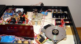
I also own a CDPRO. Please note that the magnetic clamp for the CD is probably causing harm to the sound. Please referr to the "building of a HiEnd transport..." (or something alike) thread. I'm about to change it for a mechanical system.
Try this experiment: buy a low quality CD-R pack; find one that fits tightly to the center piece (some low Q CD-R have narrower center hole) in a way that the CD does not fly when the motor is on; burn your favourite test CD and listen with/without magnetic clamp.
Then tell me if I am crazy 😉 I don't mind 😀
Cheers,
M
Of course, next project with DAC towers would include comparison between opamp output and direct DAC output, with corresponding R changes.
First of all power consumption / power dissipation goes up, the BCK buffers can't drive so many DAC chips (FAN out).
We will have to solve those power/driving issues.
If your experimental setup drove 3 DACs towers, maybe 4DAC per tower will be OK.
The improvement is clearly audible with high quality recordings that still contain sufficient spatial information, like the ones from Chesky Records.
You live near this record company:
http://www.channelclassics.com/
They use good ADC from Grimmaudio. http://www.grimmaudio.com/
I have only listened to one CD/SACD (innexpensive) and it did not sound bad at all.
Hi omainik,
I also own a CDPRO. Please note that the magnetic clamp for the CD is probably causing harm to the sound. Please referr to the "building of a HiEnd transport..." (or something alike) thread. I'm about to change it for a mechanical system.
Try this experiment: buy a low quality CD-R pack; find one that fits tightly to the center piece (some low Q CD-R have narrower center hole) in a way that the CD does not fly when the motor is on; burn your favourite test CD and listen with/without magnetic clamp.
Then tell me if I am crazy 😉 I don't mind 😀
Cheers,
M
Maxlorenz,
What was your ``reference´´ home dac when you made the recent audition/comparison with ec design dac?
What was your ``reference´´ home dac when you made the recent audition/comparison with ec design dac?
Re: interpolation / TDA1543 vs TDA1541A
The same happened to me with the 4xTDA1541 DAC. At the beginnig there were a thermal problem producing sometimes notable distortion. With a better cooling of the DACs the glitches were only on the CDs
The produced HF is theoretically not on the recording. It is HF trash. 16 times interpolation is near to the original than 8x. But it's an other chapter which version has the better sound.
I didn't find info about this in earlier posts. Perhaps the nearly 150 pages were to much for a one day lecture. Coul'd You post the circuit of your modules again? It's troublesome to search through the old posts.
Thanks
Peter
-ecdesigns- said:Just last weekend we were pretty sure there was something "wrong", as a track from Christy Baron's "Take This Journey" produced noise and a light crackling sound at high volume settings on one track. And yes, after some worrying and "faultfinding", it turned out to be a flaw in the CD recording, the DI DACs were fine.
The same happened to me with the 4xTDA1541 DAC. At the beginnig there were a thermal problem producing sometimes notable distortion. With a better cooling of the DACs the glitches were only on the CDs
-ecdesigns- said:
True, with 16 x interpolation or higher, resolution increases as illustrated with oscillograms in earlier posts, but it also means more filtering / earlier HF rolloff.
The produced HF is theoretically not on the recording. It is HF trash. 16 times interpolation is near to the original than 8x. But it's an other chapter which version has the better sound.
-ecdesigns- said:
Note that the gated DEM clock improves TDA1541A performance significantly, forget about the TDA1541A sound you are used too, it can sound so much better.
I didn't find info about this in earlier posts. Perhaps the nearly 150 pages were to much for a one day lecture. Coul'd You post the circuit of your modules again? It's troublesome to search through the old posts.
Thanks
Peter
Attachments
Hi John.
Is this your newest dem-reclock explanation to be found here? Have been looking for a while in this huge thread.
http://www.diyaudio.com/forums/showthread.php?postid=1204907#post1204907
Thanks!
Is this your newest dem-reclock explanation to be found here? Have been looking for a while in this huge thread.
http://www.diyaudio.com/forums/showthread.php?postid=1204907#post1204907
Thanks!
Hi Protos,
As I said I did not have time to listen extensivelly nor to make direct comparison. All my comments were "by memory" (wich is quite good, if I may say so).
Quick hints:
Compared to heavilly modded, battery powered DDDAC MK I (with a 16DACs tower), DI16 has wider soundstage, more armonic content, more detailed, more elegant (refined) and relaxed sound.
By contrast, my DDDAC has more colorful midrange and has a more direct, primitive and immediate sound. This is a description. Tastes differ, as you now...I may like better one DAC with a certain type of music and the other with other type of music.
Compared to my heavilly modded M-Audio superDAC, upsampled to 24/96 with Monarchy's DIP upsampler (AES from CDPRO), I would say that DI16 is more "structured" in his sonic presentation, with more organic sound (NOS quality). Detail retrieval is comparable but DI16 make it sound nicer (cleaner top end).
By contrast, my superDAC has the best bass I've heard and is very dinamic.
I need to make an "all I2S chain", instead of AES, to get the best from this transport-upsampler-DAC...if I only knew how!
All this comments to be taken with a grain of salt...
Regards,
M
What was your ``reference´´ home dac when you made the recent audition/comparison with ec design dac?
As I said I did not have time to listen extensivelly nor to make direct comparison. All my comments were "by memory" (wich is quite good, if I may say so).
Quick hints:
Compared to heavilly modded, battery powered DDDAC MK I (with a 16DACs tower), DI16 has wider soundstage, more armonic content, more detailed, more elegant (refined) and relaxed sound.
By contrast, my DDDAC has more colorful midrange and has a more direct, primitive and immediate sound. This is a description. Tastes differ, as you now...I may like better one DAC with a certain type of music and the other with other type of music.
Compared to my heavilly modded M-Audio superDAC, upsampled to 24/96 with Monarchy's DIP upsampler (AES from CDPRO), I would say that DI16 is more "structured" in his sonic presentation, with more organic sound (NOS quality). Detail retrieval is comparable but DI16 make it sound nicer (cleaner top end).
By contrast, my superDAC has the best bass I've heard and is very dinamic.
I need to make an "all I2S chain", instead of AES, to get the best from this transport-upsampler-DAC...if I only knew how!
All this comments to be taken with a grain of salt...
Regards,
M
Sonic resonators / D-I vs parallel
Hi omalnlk
Thanks for your reply [post #1468],
The sonic resonators are a bit off topic, but since they are very important for D-I DAC development, I will post some information.
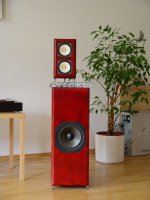
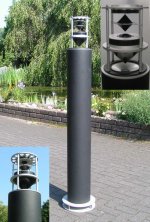
I added a photograph of different viewing angles of the sonic resonator. I also performed tests outside for fine-tuning sound coherency. This resulted in a coherent sound at large distances from the resonator.
The sonic resonators are point sources, they emit sound in a spherical pattern. When placed outside, you can walk around them, and sound won't change at all. Even at different listening heights, sound is virtually unchanged. Due to the coherency of the sound, placement of instruments and voices is also accurate, unlike most omni-directional speakers. Where conventional speakers start to color or distort sound at higher volume settings, the sonic resonators just get started. The sonic resonators have very high efficiency, 5...10W rms is often more than sufficient for normal listening levels. With 60W rms, it's like you are attending a live concert.
The heart of this unusual looking speaker is the sonic resonator, it's driven by a 7" aluminum cone bass-midrange driver. I used a small driver for fast impulse response, and for limiting the resonator maximum sound pressure.
The sonic resonator is a dual chamber resonator with an acoustic-magnetic correction element. The correction element makes it possible to generate uncolored sound with very low distortion at high volume settings. It also enables very fast response time. The tube has a bass port at the bottom. The sonic resonator also has an integrated sub-woofer that's acoustically driven, it's also controlled by the corrective element. The sub-woofer is responsible for very deep accurate bass reproduction, the major problem is preventing other objects in the listening room from starting to resonate.
The resonator housing consists of a aluminum or plastic tube. This construction is very strong and avoids refections. The bass-mid driver is mounted on top, all gray colored parts are CNC milled from aluminum. Many neoprene rubber gaskets are used for damping and sealing. Even some of the speaker chassis were completely disassembled to insert these gaskets. This eliminates all unwanted resonances. I also replaced the midrange and tweeter internal damping materials.
The bass-midrange chassis emits the sound in a spherical pattern using a large acetal copolymer cone (CNC turned).
On top of this cone, a ferrofluid soft-dome midrange driver is mounted, similar to the bass-midrange driver, it emits sound in a spherical pattern, using a smaller cone. Titanium-aluminum alloy dome mid drivers sounded "metallic", cone mid drivers had too high moving mass (slow response).
The ferrofluid titanium-aluminum alloy dome tweeter is mounted up-side down, and emits sound in a spherical pattern too, using a third cone. Soft dome tweeters couldn't cope with the high sound pressure and started to distort. Ceramic dome tweeters had too little efficiency to cope with the sonic resonator, and had limited high frequency response. Iso-dynamic drivers (traces etched on a foil, placed in a very strong magnetic field), didn't work here either (too low efficiency and very "thin" sound).
Polariser discs are added to create zones with slightly different phase, this way 3D sound information is re-constructed, up to a certain degree.
The speaker had to be tuned (mechanically and by the crossover filter), to obtain a coherent sound that appears to be generated by one single point source. This was the most difficult part of designing the sonic resonators, tuning took a few years.
The passive crossover filter couldn't be calculated accurately enough (too many parameters), calculating a bass reflex speaker is child's play when compared to a sonic resonator. There are many varying parameters, that in turn depend on mechanical settings.
so I started to roughly calculate the passive crossover filters. Next I used a special test setup with a sweep generator to dynamically tune the filters, while the chassis were already mounted in the sonic resonator. This way I got the correct filter crossover points. This was the easy part and only took a few weeks. During filter design it became very clear that the simplest filters provided best results.
Next the crossover filters and distances between speaker chassis and cones were fine tuned, this took me about a year. It became clear that due to the limitations of the filter components used, no further improvement was possible. This resulted in re-building the filter with higher quality parts like Intertechnik polypropylene plus and tin foil capacitors, stranded wire copper resistors, and hand-made air core inductors using stranded copper wire as well.
So I had to re-tune / fine tune the filter again, as these new components had different properties. It took me another year to fine-tune it. Now finally the passive filters are integrated in the sonic resonators, this also introduced some unexpected problems that needed to be solved.
Yes I have, by swapping the timing-chain module with a interconnect PCB, I could place all 8 DAC chips of the DI 8 in parallel. The sound was now less refined and very edgy. I needed to add an 8th order Butterworth filter, but it still wasn't able to match or improve D-I 8 sound at all. The D-I 8 sound was much more transparent, detailed and natural.
I already experimented with passive I/V and tube transconductance amplifiers, the result is sound coloring (sound is no longer neutral and transparent). The tube amplifier would also add significant distortion, I am not saying this couldn't sound good, tubes can produce a very nice sound quality despite the distortion. In fact, I have added a tube diff-amplifier too, but it runs in parallel with a LM4562, and there is a specific "mixing" ratio between the OP-amp signal and the tube signal. This creates a sound that no longer has the typical semiconductor or tube sound, but is much more natural and transparent.
I am trying to obtain a completely neutral, transparent and natural sound. This way all recordings, regardless of the music content will be re-produced in the best possible way.
Hi omalnlk
Thanks for your reply [post #1468],
I found linear phase to be one important issue in sound reproduction. The active speaker has a first order crossover. Coul'd You post some info about Your sonic resonators? Has the principle common sides with Bösendorfers Hornresonator?
The sonic resonators are a bit off topic, but since they are very important for D-I DAC development, I will post some information.
I added a photograph of different viewing angles of the sonic resonator. I also performed tests outside for fine-tuning sound coherency. This resulted in a coherent sound at large distances from the resonator.
The sonic resonators are point sources, they emit sound in a spherical pattern. When placed outside, you can walk around them, and sound won't change at all. Even at different listening heights, sound is virtually unchanged. Due to the coherency of the sound, placement of instruments and voices is also accurate, unlike most omni-directional speakers. Where conventional speakers start to color or distort sound at higher volume settings, the sonic resonators just get started. The sonic resonators have very high efficiency, 5...10W rms is often more than sufficient for normal listening levels. With 60W rms, it's like you are attending a live concert.
The heart of this unusual looking speaker is the sonic resonator, it's driven by a 7" aluminum cone bass-midrange driver. I used a small driver for fast impulse response, and for limiting the resonator maximum sound pressure.
The sonic resonator is a dual chamber resonator with an acoustic-magnetic correction element. The correction element makes it possible to generate uncolored sound with very low distortion at high volume settings. It also enables very fast response time. The tube has a bass port at the bottom. The sonic resonator also has an integrated sub-woofer that's acoustically driven, it's also controlled by the corrective element. The sub-woofer is responsible for very deep accurate bass reproduction, the major problem is preventing other objects in the listening room from starting to resonate.
The resonator housing consists of a aluminum or plastic tube. This construction is very strong and avoids refections. The bass-mid driver is mounted on top, all gray colored parts are CNC milled from aluminum. Many neoprene rubber gaskets are used for damping and sealing. Even some of the speaker chassis were completely disassembled to insert these gaskets. This eliminates all unwanted resonances. I also replaced the midrange and tweeter internal damping materials.
The bass-midrange chassis emits the sound in a spherical pattern using a large acetal copolymer cone (CNC turned).
On top of this cone, a ferrofluid soft-dome midrange driver is mounted, similar to the bass-midrange driver, it emits sound in a spherical pattern, using a smaller cone. Titanium-aluminum alloy dome mid drivers sounded "metallic", cone mid drivers had too high moving mass (slow response).
The ferrofluid titanium-aluminum alloy dome tweeter is mounted up-side down, and emits sound in a spherical pattern too, using a third cone. Soft dome tweeters couldn't cope with the high sound pressure and started to distort. Ceramic dome tweeters had too little efficiency to cope with the sonic resonator, and had limited high frequency response. Iso-dynamic drivers (traces etched on a foil, placed in a very strong magnetic field), didn't work here either (too low efficiency and very "thin" sound).
Polariser discs are added to create zones with slightly different phase, this way 3D sound information is re-constructed, up to a certain degree.
The speaker had to be tuned (mechanically and by the crossover filter), to obtain a coherent sound that appears to be generated by one single point source. This was the most difficult part of designing the sonic resonators, tuning took a few years.
The passive crossover filter couldn't be calculated accurately enough (too many parameters), calculating a bass reflex speaker is child's play when compared to a sonic resonator. There are many varying parameters, that in turn depend on mechanical settings.
so I started to roughly calculate the passive crossover filters. Next I used a special test setup with a sweep generator to dynamically tune the filters, while the chassis were already mounted in the sonic resonator. This way I got the correct filter crossover points. This was the easy part and only took a few weeks. During filter design it became very clear that the simplest filters provided best results.
Next the crossover filters and distances between speaker chassis and cones were fine tuned, this took me about a year. It became clear that due to the limitations of the filter components used, no further improvement was possible. This resulted in re-building the filter with higher quality parts like Intertechnik polypropylene plus and tin foil capacitors, stranded wire copper resistors, and hand-made air core inductors using stranded copper wire as well.
So I had to re-tune / fine tune the filter again, as these new components had different properties. It took me another year to fine-tune it. Now finally the passive filters are integrated in the sonic resonators, this also introduced some unexpected problems that needed to be solved.
I woul'd like to compare Your design with direct interpolation to my just paralleled DACs. Did You compare DI to parallel ICs?
Yes I have, by swapping the timing-chain module with a interconnect PCB, I could place all 8 DAC chips of the DI 8 in parallel. The sound was now less refined and very edgy. I needed to add an 8th order Butterworth filter, but it still wasn't able to match or improve D-I 8 sound at all. The D-I 8 sound was much more transparent, detailed and natural.
Perhaps there is a room for improvement with a tube transconductance amplifier for the I/V conversion. I'll try that soon. Currently i settled on a small resistor followed by a step up transformer. this combo gives for me the most natural sound. Transformers are - as you noted - non linear components, but sometimes they do magic to the sound. High frequency trrash filtering of the non-os design included
I already experimented with passive I/V and tube transconductance amplifiers, the result is sound coloring (sound is no longer neutral and transparent). The tube amplifier would also add significant distortion, I am not saying this couldn't sound good, tubes can produce a very nice sound quality despite the distortion. In fact, I have added a tube diff-amplifier too, but it runs in parallel with a LM4562, and there is a specific "mixing" ratio between the OP-amp signal and the tube signal. This creates a sound that no longer has the typical semiconductor or tube sound, but is much more natural and transparent.
I am trying to obtain a completely neutral, transparent and natural sound. This way all recordings, regardless of the music content will be re-produced in the best possible way.
Attachments
Paralleling TDA1543 chips
Hi maxlorenz,
Thanks for your reply [post #1469]
I tested 8 * 3 DAC towers in the DI-16, and it works very well. With 8 * 4 DAC towers, the OP-amp I/V stage gain should be lowered. You could try using 330R or 390R instead of 470R. You might need to modify the output attenuator too.
The TDA1543 digital inputs draw max. 0.4mA, both non-inverting and inverting clock buffers on the DI 16 core can drive approx. 24mA, so each could theoretically drive 24 / 0.4 = 60 TDA1543 inputs. The inverting clock buffer needs to drive only 4 * TDA1543, no problem here. The non-inverting clock buffer needs to drive the other 28 TDA1543 chips, this should be possible too. However it might effect jitter.
TDA1543 supply current is max. 60mA. So each TDA1543 group would require 960mA. The UA7806 voltage regulators I supplied with the DI16C PCB are specified for 1.5A. So with sufficient cooling, this wouldn't be a problem either. Note that the power supply must be able to supply 9V/2A (18VA). You mentioned using a 50VA transformer, so that's no problem either.
I have a different question for you, could you try to hook-up your CDPROII to the DI 16 core? You mentioned it had Philips format 48BCK/WS. If so, the DI 16 should function. The interpolation is not entirely correct this way, but it's only to test if the Philips format of the CDPROII is able to drive the DI 16 core directly.
Hi maxlorenz,
Thanks for your reply [post #1469]
We will have to solve those power/driving issues.
If your experimental setup drove 3 DACs towers, maybe 4DAC per tower will be OK.
I tested 8 * 3 DAC towers in the DI-16, and it works very well. With 8 * 4 DAC towers, the OP-amp I/V stage gain should be lowered. You could try using 330R or 390R instead of 470R. You might need to modify the output attenuator too.
The TDA1543 digital inputs draw max. 0.4mA, both non-inverting and inverting clock buffers on the DI 16 core can drive approx. 24mA, so each could theoretically drive 24 / 0.4 = 60 TDA1543 inputs. The inverting clock buffer needs to drive only 4 * TDA1543, no problem here. The non-inverting clock buffer needs to drive the other 28 TDA1543 chips, this should be possible too. However it might effect jitter.
TDA1543 supply current is max. 60mA. So each TDA1543 group would require 960mA. The UA7806 voltage regulators I supplied with the DI16C PCB are specified for 1.5A. So with sufficient cooling, this wouldn't be a problem either. Note that the power supply must be able to supply 9V/2A (18VA). You mentioned using a 50VA transformer, so that's no problem either.
I have a different question for you, could you try to hook-up your CDPROII to the DI 16 core? You mentioned it had Philips format 48BCK/WS. If so, the DI 16 should function. The interpolation is not entirely correct this way, but it's only to test if the Philips format of the CDPROII is able to drive the DI 16 core directly.
Hi EC-designs,
About your sonic resonators, for your effort...
I have a full-range (no XO) front and rear horn loaded project that I can't develop yet because I don't know how to use autoCAD (the only software I know of) well 🙁 ...and the full-rangers fans won't enjoy its beauty...
OK.
Here I got lost, sorry. It is not 50/50?
Playing with 64 DAC chips will not be possible (with this given buffer) then, unless we limit the max current to each chip, or add buffers to the buffers 😀
I'm only guessing...
In case of my dreamed 64DAC chips, I thought about LT1085CT-ND 3A Pos. Regulator.
Mmmhhh...that will be hard but I'll try.
Last night I listened again to DI16: it is becoming my favorite DAC. Wonderful tone and analog textures. You are right at saying that it sounds as it extracts all there is on the source. No way to test if this is true.
I think I will make an audio dedicated PC with passive cooling.
Cheers,
M
About your sonic resonators,
for your effort...I have a full-range (no XO) front and rear horn loaded project that I can't develop yet because I don't know how to use autoCAD (the only software I know of) well 🙁 ...and the full-rangers fans won't enjoy its beauty...
With 8 * 4 DAC towers, the OP-amp I/V stage gain should be lowered. You could try using 330R or 390R instead of 470R. You might need to modify the output attenuator too.
OK.
The non-inverting clock buffer needs to drive the other 28 TDA1543 chips, this should be possible too. However it might effect jitter.
Here I got lost, sorry. It is not 50/50?
Playing with 64 DAC chips will not be possible (with this given buffer) then, unless we limit the max current to each chip, or add buffers to the buffers 😀
I'm only guessing...
TDA1543 supply current is max. 60mA. So each TDA1543 group would require 960mA. The UA7806 voltage regulators I supplied with the DI16C PCB are specified for 1.5A.
In case of my dreamed 64DAC chips, I thought about LT1085CT-ND 3A Pos. Regulator.
could you try to hook-up your CDPROII to the DI 16 core?
Mmmhhh...that will be hard but I'll try.
Last night I listened again to DI16: it is becoming my favorite DAC. Wonderful tone and analog textures. You are right at saying that it sounds as it extracts all there is on the source. No way to test if this is true.
I think I will make an audio dedicated PC with passive cooling.
Cheers,
M
squeezebox -> D-I DAC ?
Hi,
I've been browsing this thread and has become very interested in -ecdesign-'s D-I design.
In case I missed it in this very long thread: Has anyone successfully interfaced a Slim Devices Squeezebox to one of these DACs? Is there any reason why it cannot be done? In the Slimdevices forum there seems to be several owners who have modified their Squeezebox to provide I2S output.
Thanks in advance.
Not quite. It core codebase is based on FreeBSD 5.0
Hi,
I've been browsing this thread and has become very interested in -ecdesign-'s D-I design.
In case I missed it in this very long thread: Has anyone successfully interfaced a Slim Devices Squeezebox to one of these DACs? Is there any reason why it cannot be done? In the Slimdevices forum there seems to be several owners who have modified their Squeezebox to provide I2S output.
Thanks in advance.
-ecdesigns- said:...
Mac OSX Panther is based on linux.
...
[/B]
Not quite. It core codebase is based on FreeBSD 5.0
Re: Sonic resonators / D-I vs parallel
Hello John,
The description of this speaker sounds really impressive. Coul'd You explain more about the acoustic-magnetic correction element?
Thank You for the info. Sooner or later I'll have to try one of Your DACs. Preferably on the CDPRO2
😎
It should be easy to transform the idea to 48 BCK/WS I²S Bus.
Ciao
Peter
Hello Maxlorenz,
Currently I have a one Year old kid - the whole audio setup is on the ceiling to save the last survived tubes and chassis 🙁 🙁 🙁
So the CDPRO with a headphone amp is the last audio toy. I'll try that soon
PLease let us know about Your results with the DI-16 and CDPRO
Ciao
Peter
-ecdesigns- said:The sonic resonator is a dual chamber resonator with an acoustic-magnetic correction element. The correction element makes it possible to generate uncolored sound with very low distortion at high volume settings. It also enables very fast response time. The tube has a bass port at the bottom. The sonic resonator also has an integrated sub-woofer that's acoustically driven, it's also controlled by the corrective element. The sub-woofer is responsible for very deep accurate bass reproduction, the major problem is preventing other objects in the listening room from starting to resonate.
Hello John,
The description of this speaker sounds really impressive. Coul'd You explain more about the acoustic-magnetic correction element?
-ecdesigns- said:Yes I have, by swapping the timing-chain module with a interconnect PCB, I could place all 8 DAC chips of the DI 8 in parallel. The sound was now less refined and very edgy. I needed to add an 8th order Butterworth filter, but it still wasn't able to match or improve D-I 8 sound at all. The D-I 8 sound was much more transparent, detailed and natural.
Thank You for the info. Sooner or later I'll have to try one of Your DACs. Preferably on the CDPRO2
😎
It should be easy to transform the idea to 48 BCK/WS I²S Bus.
Ciao
Peter
maxlorenz said:
I also own a CDPRO. Please note that the magnetic clamp for the CD is probably causing harm to the sound.
Hello Maxlorenz,
Currently I have a one Year old kid - the whole audio setup is on the ceiling to save the last survived tubes and chassis 🙁 🙁 🙁
So the CDPRO with a headphone amp is the last audio toy. I'll try that soon
PLease let us know about Your results with the DI-16 and CDPRO
Ciao
Peter
Connecting D-I DAC to squeezebox using I2S
Hi coolbiz,
Thanks for your reply [post #1477]
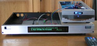
Well Actually I dug out my squeezebox 2 player, bought it years ago... The attached photograph shows it driving a DI 16 directly trough I2S 🙂
The I2S signals were located quickly: R5 BCK, R6 DATA, R7 WS. Then compatibility problems occurred as expected, they were solved by adding complicated glue logic....well, it only took 1 D flip-flop to delay the DATA signal 1 BCK period, that's all.
D flip-flop: clock connected to BCK, D input connected to the I2S data signal of the squeezebox, Q output connected to the DI 16 DATA input.
The I2S BCK signal was a bit jjiitteerryy. It could be corrected using the shiftregister reclocker.
But there are other elegant options for music player. I use a 17" iMac G5 with 500Gb HD, connected to the DI 8M / DI 16 through USB. The USBDI2S module provides exceptional sound quality by providing a very low jitter timing signal.
If you want a hi-tech remote control, use a cellphone and install Salling Clicker remote control software (Bluetooth). Now you can remote-control your computer, that can be located in another room (fan noise), and use the full colour screen of the cellphone to browse through your CD collection. The USB connection between computer and D-I DAC can be up to 5 meters (passive USB interlink) or longer (active USB interlink).
The mac mini with a 500Gb external storage drive could serve as a beautiful compact music player, no screen or keyboard needed, just remote-control it with a cellphone.
Sorry my mistake.
Hi coolbiz,
Thanks for your reply [post #1477]
In case I missed it in this very long thread: Has anyone successfully interfaced a Slim Devices Squeezebox to one of these DACs? Is there any reason why it cannot be done? In the Slimdevices forum there seems to be several owners who have modified their Squeezebox to provide I2S output.
Well Actually I dug out my squeezebox 2 player, bought it years ago... The attached photograph shows it driving a DI 16 directly trough I2S 🙂
The I2S signals were located quickly: R5 BCK, R6 DATA, R7 WS. Then compatibility problems occurred as expected, they were solved by adding complicated glue logic....well, it only took 1 D flip-flop to delay the DATA signal 1 BCK period, that's all.
D flip-flop: clock connected to BCK, D input connected to the I2S data signal of the squeezebox, Q output connected to the DI 16 DATA input.
The I2S BCK signal was a bit jjiitteerryy. It could be corrected using the shiftregister reclocker.
But there are other elegant options for music player. I use a 17" iMac G5 with 500Gb HD, connected to the DI 8M / DI 16 through USB. The USBDI2S module provides exceptional sound quality by providing a very low jitter timing signal.
If you want a hi-tech remote control, use a cellphone and install Salling Clicker remote control software (Bluetooth). Now you can remote-control your computer, that can be located in another room (fan noise), and use the full colour screen of the cellphone to browse through your CD collection. The USB connection between computer and D-I DAC can be up to 5 meters (passive USB interlink) or longer (active USB interlink).
The mac mini with a 500Gb external storage drive could serve as a beautiful compact music player, no screen or keyboard needed, just remote-control it with a cellphone.
Not quite. It core codebase is based on FreeBSD 5.0
Sorry my mistake.
Attachments
interpolation points count
Hello ECdesigns,
if 8x direct interpolation sounds in practics better than 16x Di there coul'd be an other optimuum of interpolation ponints than 8. for instance 2, 4, 8 (2, 3, 4, 6, 8, 12 for the 48 IIS version of the CD PRO 2). 16 points is already out of question after your experiment with tda1543. It could be interesting to try which count of interpolation steps gives the best sound results.
Ciao
Peter
-ecdesigns- said:
Higher interpolation factors, used in the D-I system, result in earlier HF rolloff. So 16 x interpolation causes an earlier HF rolloff than 8 x interpolation in this case.
When using maximal interpolation (64 x), the NOS DAC square wave shaped signals turn into triangle wave shaped signals, lowering the waveform energy at higher frequencies. Using 8 x interpolation is a trade-off between resolution and HF rolloff. It produces the best performance in a practical circuit.
The modified DI 16 (8 x 3 TDA1543 chips in parallel) sound quality comes very close to the DI 8 with 8 x TDA1541A and the new gated DEM clock. This is quite an achievement for these low cost DAC chips.
Hello ECdesigns,
if 8x direct interpolation sounds in practics better than 16x Di there coul'd be an other optimuum of interpolation ponints than 8. for instance 2, 4, 8 (2, 3, 4, 6, 8, 12 for the 48 IIS version of the CD PRO 2). 16 points is already out of question after your experiment with tda1543. It could be interesting to try which count of interpolation steps gives the best sound results.
Ciao
Peter
- Home
- Source & Line
- Digital Line Level
- Building the ultimate NOS DAC using TDA1541A