Re: Dutch-> American connection
You do realise the circuit is for the PCM1702 ?
tubee said:Right at this moment i am trying to connect I2S to two pcm56 dacs.
Want to try and hear this and find out if harmonic distorsion can be lowered (MSB adjust) compared to 1541.
I2S is from SAA7210, clock provided by a P2P version Kwak 7.
Found logic here on diyaudio. I/V is Pedja's AD844 stage.
The problem is i have digital noise and music, have to check glue logic.
Or clock in must be not 2.8mHz (11.28 / 4)
I don't understand why data has to be shifted 11 clockcycles.
You do realise the circuit is for the PCM1702 ?
Hi Bernard & rfbrw
Thanks for reply.
Yes i know 1702 is 20 bit, that must be the problem.
Have a copy of the AN207 where you schematic comes from for a long time allready Bernard, found out this works by a "stopped clock" operation. This schematic is intended to use from SAA7220, and clock is then 5.6 MHz, and from 7210 it is 2.8 Mhz. So will use a separate clock with divider to get it working.
Faintly between dig noise i can hear the reverbs of sounds very good,
Maybe it is a promise allready for good sound.
I'll heat up the iron first.
Hi Bernard
Thanks for suggestion.
Yes, know of that circuit too, have it between my papers near the AN207 documents, besides some service manuals etc.
Want to try I2S from cdp directly, also John can agree on that (Cs8412/8414 is not completely jitterfree and Spdif has its flaws too.)
But have a unused CS8414 lying around.
tubee said:
This schematic is intended to use from SAA7220, and clock is then 5.6 MHz, and from 7210 it is 2.8 Mhz. So will use a separate clock with divider to get it working.
Have you considered the relationship between clock and data ?
Hi pelayostyle,
Thanks for your reply [post #1259]
No, the DI-DAC kits are not available yet.
However, the PCB lay-out data (for all D-I DAC printed circuit boards) has been sent to the PCB manufacturer today.
Thanks for your reply [post #1259]
No, the DI-DAC kits are not available yet.
However, the PCB lay-out data (for all D-I DAC printed circuit boards) has been sent to the PCB manufacturer today.
Hi rfbrw
The relationship in I2S between clock/WS is: (as i understand it)
* SAA7210: 64 bit (R+L 16bit music + 16 bit subcode) with clock 2.8Mhz.
(11.2896Mhz / 4 =2.8224Mhz / 64bit gives 44.1kHz)
*SAA7220: 32 bit (R+L music) with clock 5.6Mhz.
(11.2896Mhz / 2 = 5.6448MHz / 32bit = 176.4kHz / 4 x OS gives 44.1kHz)
When 1541 is connected on 7210 (Nonos) only first 16 bits are readed after WS until 1541's registers are filled to 16 bit, subcode data wil not be used.
I think the AN207 schematic will not work correctly, clock has to be 1.4112Mhz for good operation (0.0441Mhz x 32) WS and LE is now depending/divided on 5.6MHz
It can work correct if pcm56 uses the first 16 bit only as 1541 does.
tubee said:This schematic is intended to use from SAA7220, and clock is then 5.6 MHz, and from 7210 it is 2.8 Mhz. So will use a separate clock with divider to get it working.
The point is serial clock and data are tied together. You cannot simply divide serial clock and still expect data to be clocked out as before.
Have been reading it up rfbrw, indeed those signals are tied together.
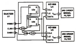
From AD's Application Note 207 for operation of AD1856 16 bit dac:
"Bringing latch Enable low after the least significant bit of ANY word latches the previous 16 bits and starts the conversion."
So I2S output of SAA7210 can be used (with subcode data) as long as the timing of LE is at the right moment, after LSB, and with falling edge LE signal for R + L.
I2S has WS signal 1 clock cycle before LSB, falling edge, and 1 clock cycle before LSB for R channel, RISING WS edge.
Simple solution that might work: Keep curent I2S-20 bit PCM logic, tap Data from another Q output on lower 74/164, at the right moment so when LE is just after LSB. Only 1 wire to remove and try them on other Q outputs for both dacs, and listen.
Saa7210-> Pcm56
I have been fiddling with inverters, trying to get own solution, only R channel works and with noise.
Here it is, also for 16 bit dacs available signals: http://www.geocities.com/nonospcm1704/universal_shifter.html
This is what i have to build: http://www.geocities.com/nonospcm1704/universal_shifter.gif
Buy Nand gate tomorrow.
Saa7210->pcm56
Have sound now. DATA R+L is tied on Q6 instead of Q2, this gives the less noisiest output with music. (but still some search noise from cdm on L) One Q output further gives only noise.
Sound of PCM56: very Nonos-like, mids are slightly distorted, think when i listen to it for 2 hours will get fatigued of it (as single 1541 nonos btw) Have to adjust MSB @ -80 dB, but don't think will help much.
Attachments
Tubee, have you already installed the MSB pot ?
With ( wrong adjustment ) or without ( most PCM56 are very bad in this mode ), sound can be horrible.
Do you have some analog filter ?
Also did you make sure with a scope that your setup is correct.
I have with dithered 1kHz 0 dB no harmonics down to -94 dB which is the dynamic limit of my analyzer.
1kHz -60dB below -60dB which is noise floor without averaging.
No distorted mids 😉
Tubee,
If you are going to connect the PCM56 to the SAA7210 or anything else, why not do it properly ? That circuit is clearly less than optimal for the '1702 nevermind the '56.
BTW, it seems to me this topic ought to have thread of its own. You wouldn't want this thread to end up like the Marantz 63/67 thread, a mishmash of every topic under the sun repeating every few 100 posts.
Ray,
Agreed, and just as a FYI I emailed you at the address which I think is the correct one with a few questions of my own, did you get that email? (I googled it, as your profile has no options for contacting you directly).
Best regards,
Sander Sassen
http://www.hardwareanalysis.com
Agreed, and just as a FYI I emailed you at the address which I think is the correct one with a few questions of my own, did you get that email? (I googled it, as your profile has no options for contacting you directly).
Best regards,
Sander Sassen
http://www.hardwareanalysis.com
I don't seem to have got your email and I was unaware my email had not been enabled. It now enabled.
BTW, it seems to me this topic ought to have thread of its own. You wouldn't want this thread to end up like the Marantz 63/67 thread, a mishmash of every topic under the sun repeating every few 100 posts.
Yes you're right. Will start another thread tonight.
Here it is, no more PCM56 stuff from me here: http://www.diyaudio.com/forums/showthread.php?postid=1122488#post1122488
PCB sets
Hi all,
Project update,
Today I received a confirmation of the DI DAC PCBs I have ordered last week.
The PCBs will be epoxy (light yellow), flash gold plated, transparent soldermask and black silkscreen. The PCBs will be scheduled for 1 March 2007. All SMD parts will be included / pre-assembled so this wil greatly simplify assembly. The DEM clock ringcore transformer will also be supplied with the DI8 mainboard. Both the DI16 core and DI8 timing module come with a pre-programmed PAL.
The DI8 comes in 2 possible PCB sets:
1) DI8 (DI8 with LM4562 output), 14 PCBs
- 1 X DI8 mainboard + DEM clock ringcore transformer
- 1 X DI8 timing module + pre-assembled SMD parts (capacitors + resistors + UHS buffers) + PALCE16V8
- 8 X DA converter module (TDA1541A) + pre-assembled SMD parts (capacitors + zenerdiodes)
- 2 X I/V diff module + pre-assembled SMD parts (capacitors)
- 1 X USB/DI2S module + pre assembled SMD parts (PCM2706 + capacitors + resistors + UHS inverter)
- 1 X DI8 power supply module + pre-assembled SMD part (resistor) + tube status LED controller
2) DI8M (DI8 with mixed mode outputs, tube + LM4562), 17PCBs
- 1 X DI8 mainboard + DEM clock ringcore transformer
- 1 X DI8 timing module + pre-assembled SMD parts (capacitors + resistors + UHS buffers) + PALCE16V8
- 8 X DA converter module (TDA1541A) + pre-assembled SMD parts (capacitors + zener diodes)
- 2 X I/V diff module + pre-assembled SMD parts (capacitors)
- 1 X USB/DI2S module + pre assembled SMD parts (PCM2706 + capacitors + resistors + UHS logic)
- 1 X DI8 power supply module + pre-assembled SMD part (resistor)+ tube status LED controller
- 1 X Tube power supply module
- 2 X Tube diff amplifier module
The DI16 comes in 2 possible PCB sets:
1) DI16 (DI16 with LM4562 output), 3 PCBs
- 1 X DI16 core + pre-assembled SMD parts (UHS buffers) + pre-programmed PALCE16V8
- 1 X USB/DI2S module + pre assembled SMD parts (PCM2706 + capacitors + resistors + UHS inverter)
- 1 X DI16 power supply module
2) DI16M (DI16 with mixed mode output, tube + LM4562 output), 6 PCBs
- 1 X DI16 core + pre-assembled SMD parts (UHS buffers) + pre-programmed PALCE16V8
- 1 X USB/DI2S module + pre assembled SMD parts (PCM2706 + capacitors + resistors + UHS inverter)
- 1 X DI8 power supply module + pre assembled SMD part (resistor) + tube status LED controller
- 1 X Tube power supply module
- 2 X Tube diff amplifier module
I will post some more information about these four PCB sets, and detailed information about each module.
DI8M configuration
DI8M
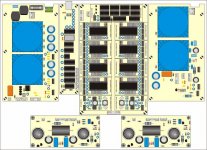
The attached drawing illustrates the DI8M configuration. On the top left is the DI8 main power supply, it can be wired for both 115 and 230V. It drives logic circuitry and the DI8 core. Remote power on/off function can be added if desired.
Next is the USB/DI2S interface, it provides both USB and differential I2S inputs. The USB circuitry includes a shiftregister reclocker, the DI2S goes straight to the DAC chips. The module automatically toggles between USB and DI2S, USB has highest priority. There are outputs provided to drive a two color indication LED.
In the center is the DI8 core, it consists of the DI8 mainboard, and a number of modules mounted on top of it. The DI8 mainboard holds all interconnections, filters for each power supply connection, DEM clock filter / attennuator and DEM clock coupling caps. The following modules are mounted on top of the DI8 mainboard: DI8 timing module, 8 x DAC module and 2 X I/V diff amplifier module.
On the top right is the tube power supply, it can be wired for both 115 and 230V. It drives both tube diff amp modules (filament voltage + high voltage). It has a integrated soft start circuitry for the filaments and a delayed power-on for the high voltage.
At the bottom are the two tube diff amp modules, necessary for the "mixed" mode. They consist of a differential amplifier (ECC83S balanced) and a cathode follower (ECC81).
DI8M
The attached drawing illustrates the DI8M configuration. On the top left is the DI8 main power supply, it can be wired for both 115 and 230V. It drives logic circuitry and the DI8 core. Remote power on/off function can be added if desired.
Next is the USB/DI2S interface, it provides both USB and differential I2S inputs. The USB circuitry includes a shiftregister reclocker, the DI2S goes straight to the DAC chips. The module automatically toggles between USB and DI2S, USB has highest priority. There are outputs provided to drive a two color indication LED.
In the center is the DI8 core, it consists of the DI8 mainboard, and a number of modules mounted on top of it. The DI8 mainboard holds all interconnections, filters for each power supply connection, DEM clock filter / attennuator and DEM clock coupling caps. The following modules are mounted on top of the DI8 mainboard: DI8 timing module, 8 x DAC module and 2 X I/V diff amplifier module.
On the top right is the tube power supply, it can be wired for both 115 and 230V. It drives both tube diff amp modules (filament voltage + high voltage). It has a integrated soft start circuitry for the filaments and a delayed power-on for the high voltage.
At the bottom are the two tube diff amp modules, necessary for the "mixed" mode. They consist of a differential amplifier (ECC83S balanced) and a cathode follower (ECC81).
Attachments
- Home
- Source & Line
- Digital Line Level
- Building the ultimate NOS DAC using TDA1541A