D-I 16 housing front view
Hi all,
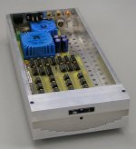
Another photograph of the housing,
The holes at the right are for cooling, the top front panel consists of a milled aluminum profile that's also used for the logo. The high-gloss stainless sheet in the center holds the indication LED, the bottom front panel consists of a milled aluminum profile. A step pattern, similar to the octal D-I DAC tube protection grid is used here.
The top cover will have ventilation slots similar to the octal D-I DAC, this is necessary for optimal cooling of the transformers and the 16 TDA1543's.
Also visible now is the space reserved for the new USB interface (at the right).
The D-I 16 housing measures 32.5 X 15 X 5.4 cm.
The aluminum parts can be annodized in different colors.
Next is designing and manufacturing the new octal D-I DAC housing, it will basically have a similar construction as the D-I 16 DAC housing, but it will be about 43cm wide instead of 15cm.
Hi all,
Another photograph of the housing,
The holes at the right are for cooling, the top front panel consists of a milled aluminum profile that's also used for the logo. The high-gloss stainless sheet in the center holds the indication LED, the bottom front panel consists of a milled aluminum profile. A step pattern, similar to the octal D-I DAC tube protection grid is used here.
The top cover will have ventilation slots similar to the octal D-I DAC, this is necessary for optimal cooling of the transformers and the 16 TDA1543's.
Also visible now is the space reserved for the new USB interface (at the right).
The D-I 16 housing measures 32.5 X 15 X 5.4 cm.
The aluminum parts can be annodized in different colors.
Next is designing and manufacturing the new octal D-I DAC housing, it will basically have a similar construction as the D-I 16 DAC housing, but it will be about 43cm wide instead of 15cm.
Attachments
D-I DAC jitter sensitivity
Hi Bernhard,
Thanks for your reply [post #1125]
Sorry I didn't comment yet, but I have been very busy as always.
Why is jitter sensitivity of the D-I DAC comparable to a NOS DAC?
Like rfbrw correctly stated, non of the individual DAC chips receive a clock frequency higher than fs.
Each individual DAC chip holds it's sample for a full WS cycle (64 * bck).
The reflected mirror image is not shifted up like with a oversampled DAC. So a D-I DAC operates significantly different when compared to a oversampled DAC with linear interpolation. Obtaining 16*, 32*, 64* and 128* real oversampling would cause big problems as jitter sensitivity increases accordingly. So a D-I DAC can easily mimic a 16...64* oversampled DAC with NOS DAC jitter sensitivity!
So, the jitter sensitivity associated with higher REAL sampling rate doesn't apply for the D-I DAC, as all it's components receive low frequency spectra compared to a oversampled DAC.
Furthermore the DAC array and the I/V converters are split-up in two groups, so each group has only half of the HF load to process. The diff amp combines both I/V output signals to the high-resolution output signal. The D-I DAC is a NOS DAC with significantly reduced quantisizing errors as the signal shape fits the original signal better than a NOS DAC, due to the resolution enhancement. As dusfor99 correctly stated, errors in a D-I system are spread over a larger spectrum, resulting in a better SN ratio.
Since the reflected mirror image is not shifted-up, output resolution is very high, and linear interpolation produces a natural HF roll-off, the D-I DAC can run without a analog correction filter to achieve optimal phase accuracy. Due to the DC-coupled design, no coupling capacitor is needed. Now a very clean signal path is obtained: DAC > I/V > Diff-amp > output signal. By using a OP-amp I/V stage, +/-25mV compliance is met, even with the TDA1543, keeping DAC chip related linearity errors as low as possible.
It also seems that you may have forgotten that I constantly compare the D-I DAC with a NOS reference DAC and several oversampled DAC's. So listening sessions also confirm, the D-I DAC jitter sensitivity is equal or less than a standard NOS DAC. The reason why I still paid so much attention to reducing jitter, is to obtain highest possible sound quality with this system.
The D-I DAC is a NOS DAC with resolution enhancement, resolution enhancement is obtained by parallel processing, enabling linear interpolation at fs. The D-I system can have much higher resolution than a DAC with oversampling, because of this parallel processing, resolution comparable to 8, 16, 32, 64* oversampling and even higher can be obtained. A DAC with 64* oversampling would have to run at 64*2.11 MHz = 135 MHz, just imagine the extreme jitter sensitivity this would cause, as 8* oversampling (16.93 MHz) already causes big problems. Constructing a D-I 64 core would just create this resolution using "slow" TDA1543's and still have jitter sensitivity comparable with a NOS DAC, just imagine what difference this makes.
After lots of experiments and measurements on different DAC types, I am pretty convinced the majority of problems caused in oversampled DAC's are caused by using relatively high frequencies and running these unattenuated trough both DAC chip's and I/V stages. The errors due to jitter seem to be created in both DAC and I/V stage as well. By keeping jitter extremely low, both DAC and I/V stage can handle this HF energy slightly better as they now have more time to settle. Easy experiment is removing the bypass cap in a I/V stage, and observe the output spectra, with a oversampled DAC it would contain significant noise, now realize this HF energy already passed both DAC chip and I/V stage, disrupting their operation.
Now have a look at the oscillograms in post #269 [27], these clearly indicate, both DAC chip's and I/V stage in the octal D-I DAC run fine and seem to have very little problems with the frequency spectra they receive.
Hi EC,
as with rfbrw who still does not agree with us that your DACs are parallel running, different opinions...
IMHO the images are moved up but with less energy and as a trade for that, you still have unmoved images, also with less energy.
Remember, your unfiltered 20k sine looks like a triangle.
Also the low level signal linearity of both TDA and PCM DACs is clearly better with oversampling.
USB / DI2S module completed
Hi all,
Project update,
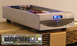
The new USB / DI2S module has been completed, it's already mounted into the D-I 16 DAC. There is just enough room for all modules, but I have to route the cables so they don't (partially) block the ventilation holes.
I added a picture of the D-I 16 DAC in action, and a picture of the new USB / DI2S PCB. I experimented with different logo backlighting, I ended up with milling a plexiglass part that distributes the light from 2 LED's, I choose blue LED's, this would combine very well with a gold coloured housing.
As for the D-I 16 sound quality, testing it on the large set in the living room revealed the true potential of this DAC, I listened until deep in the night, very impressed by it's performance. It seems the D-I 16 provides a slightly brighter sound, and the midrange sounds slightly warmer than the octal D-I DAC. Due to the OPA627 I/V stage, distortion is very low. The 16 TDA1543's ran for many hours without cooling, seems to be no problem at all.
The new USB / I2S module works fine, so it can be used in the octal D-I DAC as well, next week I am planning to complete the new octal D-I DAC PCB design, and maybe do some work on the new octal D-I DAC housing.
Hi all,
Project update,
The new USB / DI2S module has been completed, it's already mounted into the D-I 16 DAC. There is just enough room for all modules, but I have to route the cables so they don't (partially) block the ventilation holes.
I added a picture of the D-I 16 DAC in action, and a picture of the new USB / DI2S PCB. I experimented with different logo backlighting, I ended up with milling a plexiglass part that distributes the light from 2 LED's, I choose blue LED's, this would combine very well with a gold coloured housing.
As for the D-I 16 sound quality, testing it on the large set in the living room revealed the true potential of this DAC, I listened until deep in the night, very impressed by it's performance. It seems the D-I 16 provides a slightly brighter sound, and the midrange sounds slightly warmer than the octal D-I DAC. Due to the OPA627 I/V stage, distortion is very low. The 16 TDA1543's ran for many hours without cooling, seems to be no problem at all.
The new USB / I2S module works fine, so it can be used in the octal D-I DAC as well, next week I am planning to complete the new octal D-I DAC PCB design, and maybe do some work on the new octal D-I DAC housing.
Attachments
Bernhard said:
as with rfbrw who still does not agree with us that your DACs are parallel running, different opinions...
There difference is that I can defend my position with factual evidence, whereas you.......
now realize this HF energy already passed both DAC chip and I/V stage, disrupting their operation.
Also the following stages of pre- and/or poweramp get less HF in Nonos.
rfbrw said:
There difference is that I can defend my position with factual evidence, whereas you.......

Linear interpolation
Hi,
I'm completely new on this forum, so I want to say Hello to everybody 🙂
First sorry for my English, but I have very little experience.
This thread is very interesting for me and I admire how many his author, ecdesigns did in such short time! I'am impressed.
I want to ask You, ecdesigns (and others) what do You think about other way to realize such interpolation but with infinite number of points? What I mean? - about year ago I played with Delta-current linear-interpolation DAC. It is working very well in my opinion, however a DCservo is nessesery to keep DC offset near zero. I haven't made any measurements yet.
Very similar DAC was explained in 2004 on this site:
http://www.diyaudio.com/forums/showthread.php?threadid=42619&highlight
And it is only information on this idea I found ever.
It is funny, but I found it yesterday! - Earlier I was sure it was my own, very unique concept 🙂
Btw, maybe You now what happend with this interesting project. Why this thread was not been
continued. What was wrong? I can't find any message about this. Was someone more tryiing this idea in practice to?
Thank You in advance for any answer,
MarekO
Nice thread MarekO.
This referred article of last post is fascinating:
http://members.aol.com/sbench102/caps.html
now i know why i like those two Polycarbonate caps in phono stage, and the 100V biased pio's in hybrid amp!
This referred article of last post is fascinating:
http://members.aol.com/sbench102/caps.html
now i know why i like those two Polycarbonate caps in phono stage, and the 100V biased pio's in hybrid amp!
Hello MarekO,
Welcome to this thread
Well I have so many ideas and so little time, this forces me to work a bit faster.
Infinite interpolated points like described th the thread you mentioned, require very accurate analog circuits (programmable)current sources that often need to be (re)adjusted. DC / temperature drift will cause some major problems as well.
The most important things are phase accuracy, speed and harmonic balance. Circuits that create a infinite number of samples are no guarantee for better sound quality.
D-I DAC configurations
Hi all,
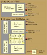
D-I DAC CONFIGURATIONS
I have added a block diagram of the final D-I DAC configurations. The PCB modules are in yellow. So for a D-I 16 DAC full version, only 3 PCB modules are needed.
For a D-I 8 mixed mode DAC full version, 17 PCB modules are needed.
Next there are several different configurations possible, as these D-I DAC's are fully modular:
1) D-I 16 minimum configuration, D-I 16 core + D-I 16 power supply, these can be placed in the transport housing. The D-I 16 core receives the I2S signal directly from the transport, like a CDPRO2 (Philips format).
2) D-I 16 mixed mode DAC full version, now the D-I 8 core is simply replaced by the D-I 16 core, only 6 PCB modules are needed.
3) D-I 8 DAC, the tube output stages are removed, now 14 PCB modules are necessary.
I/O
Mains input, Both D-I DAC's have a setting for both 115 or 230VAC.
Digital inputs, the D-I cores have a I2S input (Philips format), the USB/DI2S adds both a USB input and a differential / balanced I2S input. A separate DI2S buffer PCB module can be used to convert a existing I2S output to a DI2S signal needed for the D-I DAC's.
The universal digital audio interface PCB module can be used to connect SPDIF sources (coax or Toslink), while providing I2S performance using the integrated shiftregister reclocker, or fully synchronous reclocker using a external master clock form the transport. This module outputs the required DI2S Philips format.
Remote ON/OFF, this is a optional input (12V) that can be used to switch-ON/OFF the D-I DAC's with a external device like a control amplifier.
Audio outputs, the D-I DAC internal design is fully balanced, however the external audio outputs are RCA single-ended connections, so they can be connected to all regular audio equipment.
PROJECT PROGRESS
All PCB's have been redesigned/optimized, PCB dimensions are reduced, however some PCB's have to be manufactured and tested before a batch of PCB's can be ordered. This causes delays, but is necessary to avoid errors.
D-I 8 DAC PCB modules will now fit in the new housing.
SOME MORE CHANGES
The D-I design has been optimized even further, all power supplies will have 100V Skottky diodes 11DQ10 (IR) for low voltages and BYV96E (1000V) for high voltages, this will reduce switching noise.
D-I 8 main power supply has been simplified significantly, and has now the same size as the tube power supply
Tube output stage board dimensions are minimized, tubes are now located on the component side.
D-I core audio connector has 2 extra GND connections for easy wiring.
D-I 8 vs D-I 16
What D-I DAC sounds better? the D-I 8 or the D-I 16. The difference in perceived sound quality is marginal, both DAC's will provide exceptional sound quality.
The mixed mode version of either D-I 8 or D-I 16 will give a slightly warmer, more transparent sound. Is it worth adding a tube output stage and tube power supply? yes, if you like the most natural, harmonically balanced sound, this is certainly worth it.
When comparing the D-I 8 and the D-I 16 with the OP-amp output only, the TDA1541A gives a slightly cleaner sound due to the lower distortion, so the D-I 8 could be preferred, even if it has less resolution. But the D-I 16 comes very close, and is preferred if the budget is limited, or a more simple (compact) design is desired.
If you only want the very best, the D-I 8 with mixed mode output and TDA1541A double crowns could be considered.
Another interesting option is using the D-I 16 core in the large housing with the mixed mode output.
Hi all,
D-I DAC CONFIGURATIONS
I have added a block diagram of the final D-I DAC configurations. The PCB modules are in yellow. So for a D-I 16 DAC full version, only 3 PCB modules are needed.
For a D-I 8 mixed mode DAC full version, 17 PCB modules are needed.
Next there are several different configurations possible, as these D-I DAC's are fully modular:
1) D-I 16 minimum configuration, D-I 16 core + D-I 16 power supply, these can be placed in the transport housing. The D-I 16 core receives the I2S signal directly from the transport, like a CDPRO2 (Philips format).
2) D-I 16 mixed mode DAC full version, now the D-I 8 core is simply replaced by the D-I 16 core, only 6 PCB modules are needed.
3) D-I 8 DAC, the tube output stages are removed, now 14 PCB modules are necessary.
I/O
Mains input, Both D-I DAC's have a setting for both 115 or 230VAC.
Digital inputs, the D-I cores have a I2S input (Philips format), the USB/DI2S adds both a USB input and a differential / balanced I2S input. A separate DI2S buffer PCB module can be used to convert a existing I2S output to a DI2S signal needed for the D-I DAC's.
The universal digital audio interface PCB module can be used to connect SPDIF sources (coax or Toslink), while providing I2S performance using the integrated shiftregister reclocker, or fully synchronous reclocker using a external master clock form the transport. This module outputs the required DI2S Philips format.
Remote ON/OFF, this is a optional input (12V) that can be used to switch-ON/OFF the D-I DAC's with a external device like a control amplifier.
Audio outputs, the D-I DAC internal design is fully balanced, however the external audio outputs are RCA single-ended connections, so they can be connected to all regular audio equipment.
PROJECT PROGRESS
All PCB's have been redesigned/optimized, PCB dimensions are reduced, however some PCB's have to be manufactured and tested before a batch of PCB's can be ordered. This causes delays, but is necessary to avoid errors.
D-I 8 DAC PCB modules will now fit in the new housing.
SOME MORE CHANGES
The D-I design has been optimized even further, all power supplies will have 100V Skottky diodes 11DQ10 (IR) for low voltages and BYV96E (1000V) for high voltages, this will reduce switching noise.
D-I 8 main power supply has been simplified significantly, and has now the same size as the tube power supply
Tube output stage board dimensions are minimized, tubes are now located on the component side.
D-I core audio connector has 2 extra GND connections for easy wiring.
D-I 8 vs D-I 16
What D-I DAC sounds better? the D-I 8 or the D-I 16. The difference in perceived sound quality is marginal, both DAC's will provide exceptional sound quality.
The mixed mode version of either D-I 8 or D-I 16 will give a slightly warmer, more transparent sound. Is it worth adding a tube output stage and tube power supply? yes, if you like the most natural, harmonically balanced sound, this is certainly worth it.
When comparing the D-I 8 and the D-I 16 with the OP-amp output only, the TDA1541A gives a slightly cleaner sound due to the lower distortion, so the D-I 8 could be preferred, even if it has less resolution. But the D-I 16 comes very close, and is preferred if the budget is limited, or a more simple (compact) design is desired.
If you only want the very best, the D-I 8 with mixed mode output and TDA1541A double crowns could be considered.
Another interesting option is using the D-I 16 core in the large housing with the mixed mode output.
Attachments
Hi John
Just a small question. In configuration 1 you say the D-I core receives the I2S from the transport. Some sentences later you say "A separate DI2S buffer PCB module can be used to convert a existing I2S output to a DI2S signal needed for the D-I DAC's". What is the input for the D-I Dac's? I ask because I already have a PCB for USB to I2S conversion, but if the DAC's need DI2S I will have to buy one of your USB -> DI2S boards too.
Many thanks
Erik
I2S vs DI2S
Hi ErikdeBest,
Thanks for your reply [post #1152]
Well it's quite easy, the input of the D-I DAC core is (single-ended) I2S, the input of the D-I DAC full versions is always differential / balanced I2S. The differential / balanced I2S is necessary when longer I2S interlinks (0.5...3m) are needed like with a external DAC.
The described configuration 1 is intended for placing the DAC close to / in the same housing as the transport, then single-ended I2S will work fine. Some sentences later I referred to the full D-I DAC's that have the integrated DI2S/USB module, in this application (external DAC) the DI2S interface has to be used, so a buffer is needed to convert the transport's single-ended I2S to the required DI2S for the external D-I DAC.
Hi John
Thanks for the explanation. I looked again at the block diagram and now I understand it! It is actually quite clear, probably I was half asleep yesterday.
Although you probably will be working, I wish you a nice weekend!
Erik
Thanks for the explanation. I looked again at the block diagram and now I understand it! It is actually quite clear, probably I was half asleep yesterday.
Although you probably will be working, I wish you a nice weekend!
Erik
Hi EC,
I was just thinking along the lines of your concept the other day and stumbled across this (huge) thread yesterday when typing in some keywords in Google. It took me the better part of today to read through all the pages and get a good grasp of what you've accomplished here.
I concurr with rfbrw and some of the others here that there are some theoretical cons that might plaque your concept, but you'd have to weigh those carefully and decide whether they outweigh the pros. I'd be interested to hear your DAC if that's possible and maybe see some frequency curve/distortion plots if you have those available. I'm actually located close to Amsterdam in the Netherlands, so I'm not a whole ocean away as most of the others here are.
Let me finish off my first post in this thread with a big thumbs up for a job well done on the workmanship, very nicely done!
Best regards,
Sander Sassen
http://www.hardwareanalysis.com
If you chaps are planning a shootout perhaps you could include some of the Cd players or dacs that use linear interpolation in a more traditional way, that is precede it with a standard off-the-shelf or DSP based digital filter.
Hi SSassen,
Thanks for the compliments [post #1155]
> Yes, I am well aware of the fact that the D-I system has some theoretical cons, and I can fully understand that rfbrw and some others informed me about it. The D-I system was designed to provide a very natural sound quality, comparable with real-life sounds. What looks perfect in theory might have it's drawbacks in practical applications as practical (circuits) are often far from perfect and unexpected effects occur.
> You are very welcome to attend a listening session, this also applies for other diyAudio members that don't live too far away. Don't forget to bring your favorite CD's or even your CD player / DAC for direct comparison.
> I don't have equipment to make frequency curve or distortion plots. Of course I made some frequency measurements using a oscilloscope and a test CD containing different waveforms and frequency sweeps. My tektronics digital oscilloscope is not accurate enough for distortion measurements, it can do some rough FFT scan's but that's about it.
More important are direct comparisons with other DAC's and optimizing the audio signal, so it will produce the most natural, realistic sound.
> Thanks for the compliments on the workmanship, yes everything is hand-made, even the PCB's. If I design something, it must have high quality and it should last for many years, just like the (audio) equipment I built more than a decade ago.
Best regards,
John
Hi,
- rfbrw wrote:
-ecdesigns wrote:
Good idea 🙂
But... do not disturb the man too long as we are waiting for the kits 😀
- rfbrw wrote:
If you chaps are planning a shootout perhaps you could include some of the Cd players or dacs that use linear interpolation in a more traditional way, that is precede it with a standard off-the-shelf or DSP based digital filter.
-ecdesigns wrote:
> You are very welcome to attend a listening session, this also applies for other diyAudio members that don't live too far away. Don't forget to bring your favorite CD's or even your CD player / DAC for direct comparison.
Good idea 🙂
But... do not disturb the man too long as we are waiting for the kits 😀
Thanks John,
To get an impression of frequency response and THD, IMD distortion I'd suggest using RightMark Audio Analyzer (http://audio.rightmark.org/). This freeware software package uses a PC's sound card to gauge the performance of audio equipment, very easy to set up and it is quite reliable if you use a decent soundcard.
I'm sure a lot of us would like to see some frequency response and THD, IMD plots. If needed I'd be more than happy to assist with these, just PM or email me directly if you have any questions.
Best regards,
Sander Sassen
http://www.hardwareanalysis.com
rfbrw,
In post #130 (page 13) you wrote the following:
How'd that work exactly? What you're suggesting is you'd need some logic before the DAC to interpolate the various values and then simply run the DAC at 4Fs or 8Fs, right? Isn't that awfully close to simply using a oversampling digital filter?
Best regards,
Sander Sassen
http://www.hardwareanalysis.com
In post #130 (page 13) you wrote the following:
Why use the TDA1541A? With a 20 bit dac and the appropriate hardware one can build the equivalent of 16 dacs.Even if one must remain with the TDA1541A, one can cut the 8 dac version to 2 dacs and still retain the data rate.
How'd that work exactly? What you're suggesting is you'd need some logic before the DAC to interpolate the various values and then simply run the DAC at 4Fs or 8Fs, right? Isn't that awfully close to simply using a oversampling digital filter?
Best regards,
Sander Sassen
http://www.hardwareanalysis.com
- Home
- Source & Line
- Digital Line Level
- Building the ultimate NOS DAC using TDA1541A