Who decides whaat is 'undesirable' and where is the evidence that such an undesirable thing affects the sound?
Many of the suggestion are imho, a case of 'Gilding the Lily'. with no guarantee of an audible improvement at all.
Many of the suggestion are imho, a case of 'Gilding the Lily'. with no guarantee of an audible improvement at all.
Who decides whaat is 'undesirable' and where is the evidence that such an undesirable thing affects the sound?
In this case I decide, based on experience designing dozen's of digital audio products that are considered to deliver well above average sound quality, usually with very humble and low end parts. I also rebuild a lot of the TDA1541 single and dual DAC's in HK that were based around Thomas's PCB's and tried a lot of the suggestions not the least in this thread that made sense to me.
Many of the suggestion are imho, a case of 'Gilding the Lily'. with no guarantee of an audible improvement at all.
I am suggesting:
- Clock Lock on DEM to audio clocks
- Sufficiently large and high quality DEM filter capacitors to RELIABLY eliminate DEM ripple and errors from leakage currents
- Input signal conditioning (including reclocking) to avoid digital clock and signal feedthrough into the substrate and audio out
- RF style decoupling of known or expected high frequency signal dependent currents and glitches in short loops
- Low impedance power supplies that have a high common mode impedance and "low enough" noise which are not really that complex and which I used previously and compared to 317/337
I do not really see anything here that doesn't have a solid base in reality and individually, I have, over time tested all this in various TDA1541 based DAC's, however for a number of reasons, I never got to the point to pull it all into a single DAC.
As I am building "YATDA1541D" I am trying to do a better job this time. I wanted to see what new and interesting stuff is out there and if we can penetrate the "fog" more. I enjoy the discussion, both for clarifying things in my mind, having people call out my BS where it happens and to overall share, which always gets everyone further.
You can always ignore my posts.
Thor

Who decides whaat is 'undesirable' and where is the evidence that such an undesirable thing affects the sound?
Many of the suggestion are imho, a case of 'Gilding the Lily'. with no guarantee of an audible improvement at all.
That's an evidence, it's also true for the the pretiest girl of the prom, you never know before !
And sometimes it looks good but it's an art to make her sing !
but imagine at the end after few efforts we have not a pig with lipstick but a drunked Kobe cow with beer that is equaly looking good and tasting the same ! "Bingo !" would say Matrix 's Oracle...
I enjoy the journey !
Last edited:
Even in today's most radical designs we can see this heritage and I will posit that retaining this heritage is actually "wrong"...
This is my analysis so far. I am looking forward to comments, criticisms etc
Thor
you can always ignore my post
Thor
Well , you ask for criticisms , here you have them , based on what you said and shown here
and NO the Philips heritage was and is still not wrong , at all ....😎
.
I don't wish to ignore you: I'm not denigrating your efforts,.In this case I decide, based on experience designing dozen's of digital audio products that are considered to deliver well above average sound quality, usually with very humble and low end parts. I also rebuild a lot of the TDA1541 single and dual DAC's in HK that were based around Thomas's PCB's and tried a lot of the suggestions not the least in this thread that made sense to me.
I am suggesting:
The specifics of implementation and layout are based on my experience.
- Clock Lock on DEM to audio clocks
- Sufficiently large and high quality DEM filter capacitors to RELIABLY eliminate DEM ripple and errors from leakage currents
- Input signal conditioning (including reclocking) to avoid digital clock and signal feedthrough into the substrate and audio out
- RF style decoupling of known or expected high frequency signal dependent currents and glitches in short loops
- Low impedance power supplies that have a high common mode impedance and "low enough" noise which are not really that complex and which I used previously and compared to 317/337
I do not really see anything here that doesn't have a solid base in reality and individually, I have, over time tested all this in various TDA1541 based DAC's, however for a number of reasons, I never got to the point to pull it all into a single DAC.
As I am building "YATDA1541D" I am trying to do a better job this time. I wanted to see what new and interesting stuff is out there and if we can penetrate the "fog" more. I enjoy the discussion, both for clarifying things in my mind, having people call out my BS where it happens and to overall share, which always gets everyone further.
You can always ignore my posts.
Thor
Your posts have merit and pulling all the ideas together is a worthy aim but it would help your cause if others did likewise to endorse your findings.
There is no detailed info on the internals of TDA1541's so... lot of guesswork.Many of the suggestion are imho, a case of 'Gilding the Lily'. with no guarantee of an audible improvement at all.
Many ideas here are trite & true, since they're not new.
Thorstens (and John B) inputs are very valuable since he's gained insight through numerous commercial designs.
. . . It would help your cause if others did likewise to endorse your findings....
I did work on TDA15xx many yrs ago (started early 90s).
Summary of my findings:
Input SR attenuation:
A must. Leads to measurable and audible improvements. Many permutations.
(correct) DEM reclocking:
Affects the perceived sound quality more than I would've liked to see.
DEM capacitors:
should be of right TYPE, not necessarily of "right" audiophilian dielectric.
Best results = wide SMD types >100 nF right underneath the chip.
PSU:
Stable, standard LM3xx with pre & post passive filtering is MORE than adequate.
OS vs NOS:
I always prefered OS.
Reclocking the digital signals:
Not as trivial as u might think.
I/V conversion:
Always used passives, but later years I found that it lacked dynamics.
I now use converter with LMH6629.
Gnd pins:
No separation. Everything onto a single copper plane.
Decoupling:
Keep fast signals out of the chip.
Decouple -5 to -15 and +5 to -5.
Best of luck.
Cheers
Your posts have merit and pulling all the ideas together is a worthy aim but it would help your cause if others did likewise to endorse your findings.
I'm not running for president or any office. I'm not in any popularity contest. I'm not a Leader or tell people what to do. I do not need endorsement nor do my ideas.
I set out my reasoning in detail and my conclusions, so others can follow it and decide if I'm mostly right, or mostly wrong and do their own thing. I do not expect anyone to adopt anything I suggest unless they follow my reasoning and find themselves agreeing. If you read it and it makes no sense, then follow whatever Guru you like.
It is really none of my business, even though I may say at times, "I think this is a good idea!"
My business is to do my thing, to dance my dance. If you profit from it fine; if you don’t, too bad!
As the Arabs say, "The nature of rain is the same, but it makes thorns grow in the marshes and flowers in the gardens.
So please have fun and feel free to ignore me.
Thor
I did work on TDA15xx many yrs ago (started early 90s).
Summary of my findings:
Input SR attenuation:
A must. Leads to measurable and audible improvements. Many permutations.
(correct) DEM reclocking:
Affects the perceived sound quality more than I would've liked to see.
DEM capacitors:
should be of right TYPE, not necessarily of "right" audiophilian dielectric.
Best results = wide SMD types >100 nF right underneath the chip.
PSU:
Stable, standard LM3xx with pre & post passive filtering is MORE than adequate.
100% Agreed.
The PSU I adopt has more to do with mains/other equipment interactions than the TDA1541.
OS vs NOS:
I always prefered OS.
AMD CD-77 switchable 1 X, 1 X + SINC EQ, 2 X, 4 X with standard FIR filter.
I always preferred 1 X + SINC EQ. If just plain 1 X often 2 X or 4 X would be "different but similar preference".
Reclocking the digital signals:
Not as trivial as u might think.
Agreed, it is a system design in issue.
I/V conversion:
Always used passives, but later years I found that it lacked dynamics.
I now use converter with LMH6629.
Still best IMNSHO 1:30 or more transformer with critical loading on secondary and primary.
Again, it's a design issue. You need a transformer that can handle some DC (verify) and split the total load between primary and secondary. Only High Nickel cores work.
The transformer needs DCR, Turns ratio and core size designed to present the correct (<< 33R, preferred < 6.25R) load at the DAC, handle the DC offset current and present the correct voltage at the output and all that low distortion. The follow with J-Fet/Fet/Tube follower to suit. Nothing OTS is quite right, the required core is quite large.
Gnd pins:
No separation. Everything onto a single copper plane.
Hmmm, splits are challenging, but in this case I'm with split. Upper end commercial TDA1541 designs all split grounds and link grounds at DGND or the -15V Bulk decoupling capacitor GND pin.
Decoupling:
Keep fast signals out of the chip.
Decouple -5 to -15 and +5 to -5.
Again, agreed, but better "keep fast signals on chip or in the shortest loop.
Best of luck.
Thanks
I thank you all of you for the work you are doing and I appreciate it very much. Some points of view can be "universally recognized" and others perhaps a little "bold" and distant from the "canonical doctrine" of the TDA1541 engineers. However, I believe that I want and can only adopt some techniques addressed here, namely the attenuation of the signals digital inputs and I would like to see a comprehensive image of a double-sided simply PCB layout of the ground routing. For the rest I think I will remain faithful to:
1) Dem Grunding
2) Sim mode with CPLD (by miro)
3) lm317/337 PSU
4) AD844 + AD817 I/V converter.
5) Also my caps are: 1x 4.7uF + 1x 1uF + 5x 0.47uF
6) Not Oversampling (which you have already explained to me is not ideal with DEM GRUNDING implementation which instead requires 4xfs. 7) Maybe for point 6 I could ask Miro to reprogram the CPLD code to get 4xfs.
6) does not hold IMHO. As I pointed out several times, the DEM frequency does not need to be 4xfs. The first requirement is it is advised to be >2xfs and < about 200...250 kHz. The second requirement is that the filtered DC should not move, and that implies a symmetrical, stable, jitter-free DEM oscillator. I am not quite sure about the first requirement, we have seen 50 Hz DEM clock working. The DEM capacitors and internal current source form a filter, so simple. There should be DC or at most <<1/2 LSB (90 microvolts) on the DEM pins. Filter for that and you are done.
Ok...so...4xfs ( Grunding used) is no indispensable?
Please can you explane me how can obtain 2xfs?
Please can you explane me how can obtain 2xfs?
I never tried sim mode, but I think it is the same. It is LE not WS. The 2.2k should go to the output of the frequency divider that scales down the BCK. But I haven't tried it.

6) does not hold IMHO. As I pointed out several times, the DEM frequency does not need to be 4xfs. The first requirement is it is advised to be >2xfs and < about 200...250 kHz.
Actually, DEM causes distinct tones at Fdem/2 and Fdem/4.
I stated that to avoid low level (< -100dB) tones from DEM, we have to select a DEM frequency that makes sure that the Fdem frequency is selected that Fdem/2 < 30Hz or Fdem/4 > 15kHz to limit any chance of audibility. The level of these tones also depends on the DEM filter capacitors (value, ESR).
This suggests Fdem < 60Hz or Fdem > 60kHz.
A second issue is number of DEM cycles per sample. With Fdem >= 4 X Fs all 4 DEM states are used in a single sample.
Again it's not as such an absolute requirement, but an if A then B kind of thing.
Another issue is that Fdem should be stable with stable duty cycle.
All the above requirements are fairly easily met by synchronising Fdem with a multiple of Fs or at mains frequency.
That is not an absolute requirement, just some easy to implement techniques.
If we want to be contrarian, we could run the DEM clock from a totally free running LC oscillator using some germanium transistors at 8kHz. It's not something I'd recommend, but as long as you deal with the consequences in your design, there is no reason it cannot work well.
The second requirement is that the filtered DC should not move, and that implies a symmetrical, stable, jitter-free DEM oscillator.
Not really, as long as as the DEM filter capacitors are of a sufficiently large value, the DEM clock becomes immaterial, even high jitter and asymmetry are not consequential in that case, the a
There should be DC or at most <<1/2 LSB (90 microvolts) on the DEM pins. Filter for that and you are done.
Something like that, yes.
That is the ACTUAL requirement, a stable DC at the DEM Filter capacitor pin. Including as low leakage as possible (no more than a few 10nA) from each DEM Filter pin and the ability to sink pulses of ~ 10nS-20nS.
How it is achieved, that is down to individual design.
And if it is not designed in like this, there will still be music, only there will be more distortion, largely of a poorly predictable kind. I consider this undesirable, but some may consider it desirable, if so the design give the "right amount" of this.
Thor
Last edited:
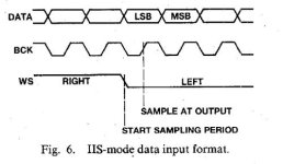
So WS does it stay connected like this?
No. The sync circuit should not be linked to WS if using no oversampling.
While bck must be divided by 16.,should the rest of the connections in SIM mode remain identical?
You MUST use IIS BCK to divide down, not SIM BCK. SIM BCK is usually stopped clock, so the DEM system would stop for part of each sample.
IIS BCK is normally 64 X Fs. Divide by 16 using a suitable IC (e.g. 74LVC161) gives 4 X FS.
One problem of the Grundig DEM sync is that it injects a net disturbance as FDEM into the DAC.
Using the Tubee style balanced clock feed eliminates this issue and the net current flow is balanced and no additional disturbances are added. In this case a pair of 74XX74 make a better divider because they have a "balanced" output.
It is also possible to use any particular MCK and divide this to a fixed FDEM (e.g. 22.5792MHz / 24.576MHz divided by 128 gives 176.4kHz/192kHz).
Thor
For those who understand more than me...that is all of you!🤣🤣
Forgive me for asking, I do not mean to imply anything about you, but do you actually understand what circuits do or do you do "solder by numbers" without actually understanding the technical side of what the circuit actually does?
Because most answers you have been getting (and all I write) are for people with a significant understanding of the circuits.
Trying to apply anything discussed without understanding is not a good idea.
If you need a complete design to copy "solder by numbers" wait for diyiggy's PCB.
Thor
- Home
- Source & Line
- Digital Line Level
- Building the ultimate NOS DAC using TDA1541A