I tried Bck dividing DEM Sync at 176.4 KHz on the Aya from Audial (Pedja Rogic) . I found the passive way whatever it is never exactly 176.4 KHz with a 470 pF capacitor that is 1% to 2% precision, gave better sonic result. (14 DEM decoupling pins at 0.1 uF). There are oddly differences when you use a FKP2 or a styren or a silver mica smd direct on pins 16/17... it is voicing details for each one hifi whole setup imho, marginal though still important sonically.
We should know in the project how we must stream according the definitive layout chosen : NOS, x4 (software or IC) ... Cause also the more versatile the pcb the less good on layout point of view. And it is as well for layouting the DEM sync circuitry on the pcb (placing the smd, traces, shift registers cabling).
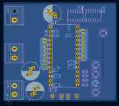
Notice in the pcb layout it is very easy to swap from lactive to passive cause the //resistor of Thorsten's schematic to pin 16/17 can be populated by a capacitor instead; and the further serie capacitor avoided (which makes it passive DEM clock, aka free running DEM Clock.
Btw I don't remember if John from ECDESIGNS used both the 6k8 R pin 16/17 to -15V stopping internal discrete osci and a passive cap still to prg the DEM clock frequency at the same time ? Whatever a pF // air capacitor to trim, it was hard to lock at the good frequency because heat variation of air pF value swang ! Certainly a detail as we use from half of the 80s the passive DEM with good sounding result enough.
I made something modular to test accordding Zoran input in order to test in real world (yes, with all the bias of the listeners).
In that not finished yet layout of a core pcb (have to finsih the decoupling scheme and the sifts register cabling, haven't had time since one month) , the violett is at the top side and the blue at the bottom side of the 6 layers. It is seen from the bottom so you can't see the top traces or the inner layers ones, just the bottom ones.
You can see it is very easy both to use passive or active DEM Sync from the Bck (can be eventually changed to come from Lrck pin, modular or not thanks to vias and jumper smd trace as you see). With an Uf-L or else plug to be populated you can also use the MCK (though the flip flop must be wirered differently (3d wires pins to pins ? After all it is a pcb for POC and tries different solutions, not a definitive one with better layout (no stacking 14x DEM board for instance)
Notice the 2 headers near the bottom decoupling 14 smd traces in order to stack a board with lythic decoupling cap (Zoran's idea) in order to try different DEM decoupling strategies. Notice a 6 layers migth be overkill for a core trying pcb because the cost at printing. 4 layers alsso feasible though asking even more trade offs.
We should know in the project how we must stream according the definitive layout chosen : NOS, x4 (software or IC) ... Cause also the more versatile the pcb the less good on layout point of view. And it is as well for layouting the DEM sync circuitry on the pcb (placing the smd, traces, shift registers cabling).
Notice in the pcb layout it is very easy to swap from lactive to passive cause the //resistor of Thorsten's schematic to pin 16/17 can be populated by a capacitor instead; and the further serie capacitor avoided (which makes it passive DEM clock, aka free running DEM Clock.
Btw I don't remember if John from ECDESIGNS used both the 6k8 R pin 16/17 to -15V stopping internal discrete osci and a passive cap still to prg the DEM clock frequency at the same time ? Whatever a pF // air capacitor to trim, it was hard to lock at the good frequency because heat variation of air pF value swang ! Certainly a detail as we use from half of the 80s the passive DEM with good sounding result enough.
I made something modular to test accordding Zoran input in order to test in real world (yes, with all the bias of the listeners).
In that not finished yet layout of a core pcb (have to finsih the decoupling scheme and the sifts register cabling, haven't had time since one month) , the violett is at the top side and the blue at the bottom side of the 6 layers. It is seen from the bottom so you can't see the top traces or the inner layers ones, just the bottom ones.
You can see it is very easy both to use passive or active DEM Sync from the Bck (can be eventually changed to come from Lrck pin, modular or not thanks to vias and jumper smd trace as you see). With an Uf-L or else plug to be populated you can also use the MCK (though the flip flop must be wirered differently (3d wires pins to pins ? After all it is a pcb for POC and tries different solutions, not a definitive one with better layout (no stacking 14x DEM board for instance)
Notice the 2 headers near the bottom decoupling 14 smd traces in order to stack a board with lythic decoupling cap (Zoran's idea) in order to try different DEM decoupling strategies. Notice a 6 layers migth be overkill for a core trying pcb because the cost at printing. 4 layers alsso feasible though asking even more trade offs.
Attachments
Last edited:
There is a theoretical possibility (yet to be proved) that the DEM oscillator might interfere with the BCK and/or with the LE signal, causing spurious signal in the audio band. This could be be due to on-chip leakage, ground bounce, whatever. I think that syncing the DEM oscillator to LE signal (á la Grundig in 4x OS) or to the divided MCK or BCK would not harm, it does not increase coplexity too much. In any case, I would not go beyond 176.4 kHz, regardless I don't believe in the "4-times sample rate" rule. Even 50 Hz DEM clock worked fine, with properly sized decoupling capacitors, didn't it? Most important is perfect (I mean rigorously perfect) 1:1 symmetry of the DEM oscillator duty cycle. It should be also jitter-free, naturally.
It does , and yes sizing the cap is a thing , I personnaly change my UKL 100 uf /25 v on all the pin by another 100 f 50 v for the first 6 pin and 220 uf /25 v on the pin 13 and 18 , it brings down to noise floor the few dB of the 60 Hz and some less harmonics too
.
Hello @ThorstenLPOC = Piece of Carp
I have 3 Sony players with non-A chips. It will be a while, I'm hoping before X-Mas.
Thor
I built miro dac with TDA1541 NON-A and without OSC cap high frequency is noisy, when use 680pf for pin 16,17 the sounds is clean.
In sony player used osc cap for non-A?
HiHi,
I said I would show the "Super Capacitor" version of the power supply that is fully split A/D. including analog stages.
Here you go:
View attachment 1358777
Regulation is simple. The main AC Impedance and Noise specifications are down to the super capacitors. The rest of the circuit is made simple, with common mode noise conduction significantly reduced.
Most TL431 are actually "protection" circuits for start-up.
Only the +5V ones should be active.
Thor
If You insist on LM317 ICs I can suggest to add just one same IC for each one, for "Tracking pre-regulator" configuration.
?
I made it once and it was better than classic one IC regulator...
.
One note about 317 specimens:
Contemporary versions are somehow "not good". to not to use other word starting with "Sh" 🙁
I had a mush better results with "old" Motorola 317/337. But it may be harder to find.
Anyway, if Motorola is unobtainable i suggest to use some types with better, more mass, integrated body heatsink?
.
And, 🙂
You switch to 2 x power suply for A and D for 2 x +5V A/D and for 2 x -5V A/D.
Sharing common "GND" potential points (L connected)
I draw earlier posted in topic, modular schematic but for only 2 x -5V A/D line power. Which was considered as booth A and D function...
I think the same treatment for 2 x +5V for A + D power, "sharing" the "GNDs" points is better.
And it is not huge addition and complexity for one transformer and PS units.
.
I will draw the concept SCH
.
TDA1541A deserves very good treatment in that way for sure 🙂
Thanks.
Hi thanks for the answer.There is a theoretical possibility (yet to be proved) that the DEM oscillator might interfere with the BCK and/or with the LE signal, causing spurious signal in the audio band. This could be be due to on-chip leakage, ground bounce, whatever. I think that syncing the DEM oscillator to LE signal (á la Grundig in 4x OS) or to the divided MCK or BCK would not harm, it does not increase coplexity too much. In any case, I would not go beyond 176.4 kHz, regardless I don't believe in the "4-times sample rate" rule. Even 50 Hz DEM clock worked fine, with properly sized decoupling capacitors, didn't it? Most important is perfect (I mean rigorously perfect) 1:1 symmetry of the DEM oscillator duty cycle. It should be also jitter-free, naturally.
I think that the PHI/Grundig LE based 176.4KHz are fixed fo.
Because CD format is 44.1KHz and they use OS SAAxxxx digital 4 x OS.
And that is more related to audio band and original SR/2 audio HF?
For max sample rate HF -3db fo will be 1/2 so it is 176.4KHz still (or 192KHz for 48KHz base)
.
Anyway I was asked because it seems to me that is best solution to use some counter and derive DEM 16.17 Fo
from MCK
Since the C on MSB to MSB-7 pins are calculated for say 176.4KHz,
They are not.
My calculations only state the MINIMUM capacitance that is likely to attenuate the worst case ripple from the DEM circuit to a level where it is less than 1/2 MSB, at a given frequency.
So Capacitors are the lowest values that should be used for this circuit, not a "tuned" value.
You can use more capacitance, you can use less. Less capacitance will best be used with DEM frequencies that integer multiples of the sample rate with minimum recommended ratio being 1:4, that is Fdem = 4 X Fs. but if not used with a reliably locked DEM clock the result is simply greater error than 1/2 LSB with the worst case tolerances in the DEM circuit.
Would it be good to have also constant Fo of 176.4KHz at DEM oscillator (pins 16, 17)?
Note:
Only in case of 44.1KHz Sampling rate,
Well, if you only ever see 44.1kHz Fs (inside a CDP), then setting Fdem to 176.4khz is valid. It can be done while bypassing the SAA7220 (but retaining it in place) and using SAA7220 BCK to drive a Grundig DEM Sync.
In every Sample rate increase, the external DEM oscilator Fo is higher for SR x n times
while DEM MSB pins remain fixed 176.4KHz
This can be done. The consequence is that for each sample less than 4 DEM Cycles occur (at 8X Sample rates we get 4 DEM cycles in 8 samples).
It means the potential for errors at each sample is increased. If using my minimum value calculation errors should be reliably < 1.2 LSB, in practice probably significantly less.
There is a theoretical possibility (yet to be proved) that the DEM oscillator might interfere with the BCK and/or with the LE signal, causing spurious signal in the audio band.
I don't think this exists.
BUT there is a real and proven mechanism by which BCK, Data & LE signals can interfere across the whole chip. Namely the planar PNP input transistor with collector to substrate has a large collector to Base (Miller) capacitance that is charged /discharged at every edge via the substrate.
The substrate has a significance resistance to either GND pin and capacitively couples into every part of the IC.
Another proven mechanism causes DEM Clock sub harmonic leakage into the Audio Output, that is the ripple at the DEM Filter capacitor pins being insufficiently attenuated by the DEM Filter Capacitor.
Both are very real.
If both mechanisms are active at sufficient levels (e.g. a "cooking" SAA7220 + TDA1541 design with 100nF capacitors and free running OSC will cause beat notes, the relatively poor stability of the DEM oscillator will cause low level IMD that can fold back into the audible range.
Syncing the DEM clock to audio clocks of at least 4 X Fs causes these subharmonic edges to line up with the audio clock edges.
Using larger Cdem Values attenuated the DEM clock feedthrough into the audio output.
Using slew rate and voltage swing limited input signals (at the simplest a series resistor of ~1.32k, when modifying existing gear) attenuates audio clock/signal feedthrough.
So a minimum mod set for existing DAC's might be Grundig DEM sync and 1.32k resistor (~10MHz lowpass) in the Data/Clock lines. Improvements by this simple set of measures is bound to be substantial, I will be able to test on my PM-75.
In any case, I would not go beyond 176.4 kHz, regardless I don't believe in the "4-times sample rate" rule.
There is no "4 X Rule", just in this case a number of mathematical constructs sum reliably back to zero (though the ~10...20nS switching glitch at fDEM throws a spanner into the practical works), allowing in theory the DEM Filter capacitors to be discarded.
We can look at two unrealistic but instructive cases.
1) Cdem = oo - this means once the system is stable (long after the end of the universe) we can disable not just DEM switching but any current from DEM.
2) Fdem = oo - this means we do not need Cdem at all.
Even 50 Hz DEM clock worked fine, with properly sized decoupling capacitors, didn't it? Most important is perfect (I mean rigorously perfect) 1:1 symmetry of the DEM oscillator duty cycle. It should be also jitter-free, naturally.
As the DEM clock is divided by a ring counter a precise 50% duty cycle is not very important. Having a very stable frequency however is important. Dividing BCK will do that, as will dividing MCK. One will create a 4X clock, the other a fixed clock.
Due the limited switching speed of the transistors in the DEM circuit, the higher the DEM frequency the greater the frequency of these glitches, which cannot be considered reliably independent from the remaining IC state. Everything is a trade-off.
The glitches in my view are less relevant if layout and DEM/AOL/AOR/+5V decoupling are handled right, this can even be done in modifications of existing gear. Kapton tape insulator and copper Foil to make a AGND or (preferred) -15V plane every decoupling capacitor is bonded into below the IC. So the DEM frequency becomes a little less relevant.
I tried Bck dividing DEM Sync at 176.4 KHz on the Aya from Audial (Pedja Rogic) . I found the passive way whatever it is never exactly 176.4 KHz with a 470 pF capacitor that is 1% to 2% precision, gave better sonic result.
I find it is easy to fool oneself. What does "better sonic results" really mean? I prefer precise and repeatable descriptions of changes to sound quality / sound quality impairment changes.
We should know in the project how we must stream according the definitive layout chosen : NOS, x4 (software or IC) ... Cause also the more versatile the pcb the less good on layout point of view. And it is as well for layouting the DEM sync circuitry on the pcb (placing the smd, traces, shift registers cabling).
I see no difference between 8 X OS @ 48kHzand Non-OS at 384kHz. Do you?
Btw I don't remember if John from ECDESIGNS used both the 6k8 R pin 16/17 to -15V stopping internal discrete osci and a passive cap still to prg the DEM clock frequency at the same time ?
Final version, passive divider. 10k from CMOS output positive to AGND, 2.2k to -15V. Problem, with these values we get 1.5mA glitches at Fdem into -15V.
I built miro dac with TDA1541 NON-A and without OSC cap high frequency is noisy, when use 680pf for pin 16,17 the sounds is clean.
In sony player used osc cap for non-A?
No cap. But I do not use these units, they are Falun Gong prisoners ready for organ harvesting.
If You insist on LM317 ICs I can suggest to add just one same IC for each one, for "Tracking pre-regulator" configuration.
No point. You could also use other IC's, e.g. 7810 for the +/- 5V Digital.
They do not need to be low noise or low impedance. Just hold DC voltage steady.
The DCR of inductors and the Super Capacitors capacitance create an ~0.01Hz lowpass with around 38dB attenuation of noise at 10Hz and a second roll-off above ~150Hz, reaching ~54dB attenuation at 1kHz. The regulator is basically immaterial in the context.
Add to that the common and differential mode noise attenuation of mains noise to ~2.8mV PP before the regulator and really almost any reg will do. This is actually the point of this otherwise overly complex PSU. Let the supercapacitors totally dominate noise and impedance, build the highest possible firewall for unwanted noise on the mains side.
And, 🙂
You switch to 2 x power suply for A and D for 2 x +5V A/D and for 2 x -5V A/D.
Sharing common "GND" potential points (L connected)
I draw earlier posted in topic, modular schematic but for only 2 x -5V A/D line power. Which was considered as booth A and D function...
I think the same treatment for 2 x +5V for A + D power, "sharing" the "GNDs" points is better.
And it is not huge addition and complexity for one transformer and PS units.
.
I will draw the concept SCH
Remember, +5V to -15V is the main loop for audio, it needs a fast low impedance path. AGND is the supply for the DEM circuit and -15V is the AC Reference/GND for the DEM circuit.
AOL/AOR and +5V are current outputs for current from DEM. There is no analogue supply current here, but 8mA in total flow here, out of ~22...27mA total current in -15V, the audio signal current.
So
-15V = 22...27mA
AGND = 22...27mA - 8mA = 14...19mA
AOL = 0....4mA
AOR = 0....4mA
+5V = 0....8mA (sum of inverse of AOL/AOR current)
where Iaol +Iaor + I5v = 8mA
Then +5V is Digital CML supply (kinda PECL) and -5V is supply for CML (ECL with - supply) driving bit switches. Reference DGND.
+5V & -5V draw similar current with less for +5V.
Thor
in my setup the DEM sync from the BCK makes the bass fater, less defined, less tigth : like a sorta of veil if that word makes sense. YMMV.
I am not sure it was made on the shematic like the one discussed here for that task.
I am not sure it was made on the shematic like the one discussed here for that task.
in my setup the DEM sync from the BCK makes the bass fater, less defined, less tigth : like a sorta of veil if that word makes sense. YMMV.
Or it actually makes the bass more "real" but your previous system was tuned to towards the leaner bass of the DAC without DEM sync?
Not having a go, just noting the same audible difference may be interpreted differently.
Thor
No because i have tons of dac to benchmark.
Btw Pedja you know well, wrote à paper on active dem sync vs free running Dem. I know he uses ESL speakers and traditioanal one as well.
Btw Pedja you know well, wrote à paper on active dem sync vs free running Dem. I know he uses ESL speakers and traditioanal one as well.
Last edited:
Interesting..... . . . in my setup the DEM sync from the BCK makes the bass fater, less defined . . . .
My observations are exactly the oppsite:
I used a slightly modified version of the active synchronous DEM a la Henk Ten Pierick.
There was a repeatably notable improvement in percieved dynamics ( slightly deeper and "snappier" bass, and better resolved higher tones ) all presented in a more "relaxed" manner.
The standard solution of 470pF - 680pF DEM cap produced an immediately notable harsher, less flowing signature.
//Alex
PS:
I use an older TDA1541A ---> HSH87xx
Maybe later productions might be less sensitive ??
Last edited:
Well, I first would have pulled thr speakers forward a few inch and listened again.No because i have tons of dac to benchmark.
Btw Pedja you know well, wrote à paper on active dem sync vs free running Dem. I know he uses ESL speakers and traditioanal one as well.
I experimented a lot with free running and synchronised, I never found free running preferrable. I used both HtP's and John's final design.
Thor
I believe you, maybe something turned wrong as for me it was too fat. Dunno. Anyway on the layout as I showed it is easy to swap from Active sync to free running DEM with thz smd trace for the // resistor to pin 16/17. I think everyone will layout his pcb with that close to these pins.
Interesting....
My observations are exactly the oppsite:
I used a slightly modified version of the active synchronous DEM a la Henk Ten Pierick.
There was a repeatably notable improvement in percieved dynamics ( slightly deeper and "snappier" bass, and better resolved higher tones ) all presented in a more "relaxed" manner.
The standard solution of 470pF - 680pF DEM cap produced an immediately notable harsher, less flowing signature.
//Alex
PS:
I use an older TDA1541A ---> HSH87xx
Maybe later productions might be less sensitive ??
Hi, I don't think so as I have chips from the beginning to 1997, also Taiwann, an S1. They do sound not the same, but here it was obvious went wrong in the DEM sync setup I tried to be as not good.
Indeed most of people reported the same feeling as you or Thorsten, with at a first glance a preference for the DEM Sync. And again there is several way to do it. If you can find the AYA 2 or 4 manual as a recent customer (mine is from 2014) you could check the shematic and btw it was better integrated (layout) in the further AYA 2 DS version that came one year or two after the 2014. I had to hack the bck signal with a coax cable of 1.5" inch took from a scalped uf-l cable (damit their plugs are so fragile, I understand why people prefer the bulky screwable SMA connector ! but more expensive). So my try is not representative.
I put here the paper from Rogic about free DEM vs active for the thread documentation : https://www.audialonline.com/community/topic/tda1541a-dem-clocking/ . This is an interresting point of view more. Both should definitly tried. I suspect as there is variation from chip to chip than the free DEM clock not react the same between the fe pF variation of each cap and TDA1541A variations too (and of course between different dielectric and form factor (smd silver mica; no metalized Wima 5 mm pitch, etc) ; a detail though here vis à vis of all the rest of the development (decouplind 14x; I/V stage; front endattenuation, pcb layout, PS, etc. Even with a verroboard the close holes are 2.54 mm pitch from eachothers & between the pin 16/17...
Last edited:
with minimum recommended ratio being 1:4, that is Fdem = 4 X Fs
But that is what i trying to say?Well, if you only ever see 44.1kHz Fs (inside a CDP)
The ratio is not 1:4 but 1:1 of Fs
because - most probable the papers considering the practical aplicalications in CD players in OSmode with SAA chip.
.
To simplify
I think that external DEM Fo should be fixed value to maximum 176.4KHz for all sampling rates.
Last edited:
It's the recommended Fdem from Philips V d Plaasch OEM designers paper. Above 200 K hz it noiser and IIRC it is less good below 150 K hz.
Most of our reccordings are 44.1 K Hz and as noticed x4 and x8 certainly sounds the same with them in ABX situation.
With the fixed values of the 14 Dem sync from T Loesch I understood there is no dependancy with the Fdem seen at pin 15/16.
Indeed the said Grunding or like was a near 160 something K Hz because indeed it was already oversampled x4. So Here FDem equaled Lrck.
@Zoran, if you have 192 K hz and more material it should work less good or the ripple handled by the 14 x Dem from Thor is good enough for that whatever it is 88,2 K he to 352 K hz (and ultimatly 388 K hz) ? Or always divide the Bck per 8 or 16 'do not remember the circuitry discussed 2 months ago now ?!
Mck dividing will be always a fixed value but certainly good if the clock is not too far ? Anyway we have now a schem with two 74H74 flip flop already ! Want to do sligthy different Zoran ?
MCK is not far away, actually it is used for recklocking inputs. So it is on boardMck dividing will be always a fixed value but certainly good if the clock is not too far ?
but BCK i2S is more remote than MCK, because it is on the input on I2S-TimeSim transcoding PCB...
There is some interest for D3a tube. In triode mode.
I collect some informations and made few PSpice models.
I made spice models for G2-A, G3-K with Telefunken and Siemens datasheet measurements.
Note that in this configuration capacitnces are different...
.
Also I made a model with Vinil Saveour measurements for G2,G3-A
As for some bartola Siemens specimen type measurements check.
.
Other 2 models are from barola measurements and they are prety close, but not the same.
.
All spice models are in the form of .inc (incloude) file and they are in .zip archive.
Attachments

Not sure I understand, Master clock may exist if an output plug/pins on the Async USB board or a near Master clock pcb (IanCanada clock, FifoPi, JLSounds, etc ?) ? could be relativly far for a single ended clock line ?MCK is not far away, actually it is used for recklocking inputs. So it is on board
but BCK i2S is more remote than MCK, because it is on the input on I2S-TimeSim transcoding PCB...
For instance in my everydays DAC, The Masterclock is at 20 cm linear from the TDA causse all the pcbs and uf-l wires : basicly on mine after a Fifo buffer it is reclocked by a masterclock then goes with ufl lines to the masterclock slaved simultaneous/stop clock board then agaain 4"uf-l lines to the core pcb uf-l plugs then 2 or 3 inches from the on boardg uf-l to the TDA1541A pins. I know the PCM chips are very less sentive to jitter, maybe it is just okay ?
Are you talking of such lengths ? Certainly details, Though a good front end is a major progress all here have experience with this old chip (Good clocks, attenuation, better popular understandment of pcb layouting....)... We are already at 1/4 of the XXI century (I know it is sounding as old fart, but I have not experienc"ed the youngest makes better, ahaha, joke, lol )
Last edited:
@Zoran, it is certainly not the bad tube for that task, some may disagree, but there is imho enough disparity between two D3A tubes that a circuitry that manage that is needed or some trimming according the circuitry perhaps ! Some say it doesn't oscillate, some say it needs ferrite beads on socket tubes pins !
Not a tube for all, as I said on the other thread I could be happy with an E188CC followed by a good 5687... but all of that became rare, expensive for what is is honestly (snobery nowadays ?).
At all, we spend too much time to discuss all the possibiilities (creativity from T & Z), for now a lot of critism, attacks, were made, but still no pcbs and btw by the first that critic whom showed nothing. Time to populate boards ! 🙂
Seen from my Asics, it will end with a core pcb and multiple PS, I/V, and maybe front end pcbs. Audio became expensive (the parts of the guaranted distributors), but it is anyway better whe all is on a standalone pcb. YMMV and certainly those old chips are more tolerant to this (but be warned about stacking and antenna effects). Some of course will make their own not shered pcb. Thor said it is ok with verroboard and copper/kapton tapes is good enough (if not the same at the end from the ears perspective)
Last edited:
TDA1541 Modkateer Redux
Well, this analysis overall proved worthwhile. While trying to understand what goes on and why a certain design aspect changes the sound quality offends some in this thread, overall I think it helps.
When it comes to DEM filtering and clocking, we have seen the OP (John / ecdesigns) tried out anything from no DEM filter capacitors and a several MHz DEM frequency to 100uF Electrolytic Capacitors (not even low leakage types) with 50Hz DEM Clock. Not once did he report "bad sound", so I conclude the TDA1541 sounds pretty good no matter what you do.
We discussed a lot for new designs, but for those with existing DAC's based on China PCB's, existing classic gear etc. these are usually not feasible. Let's see what we can do.
After our expedition deep into the TDA1541 nether regions, I would say that this early 90's design by Grundig (for Philips) holds up well:

The 1uF MSB Cap's are spot on. DEM Sync to WCK from SAA7220 also.
So if we modify some existing gear this is a good start.
With my recommendations it get's us here:

Added LC filtering for SAA7220 & TDA1541 Supplies and use of large value Os-Con. Ideally there is a Kapton tape + copper tape) DGND Plane under the SAA7220 to the TDA1541 Pin14.
Series resistors in the digital signals to slow down the edges.
TDA1541 uses 1uF for the 2 MSB Pin's (easiest) to minimise DEM ripple entering the audio circuit.
I/U stage Op-Amp changed to OPA2156 (or OPA1656). Here deliberately there is no offset current. The Op-Amp output is thus forced to ~ +3V and biases the output stage naturally into SE Class A. The I/U stage also has a pair of 10nF capacitors to DGND that help to avoid the Op-Amp slewing at fast edges.
Little item easily missed, the capacitors on +15V Op-Amp are returned to +5V, not AGND. Ideally one Dual OPA is used for the first stage and a second for the Output. In that case the output gets separate decoupling.
The output stage is a simple buffer, with DC removal (1uF Film Cap) and classic SK lowpass. The output DC will be a few mV worst case, so coupling capacitors can be omitted. Build out resistors (say 51R) are needed.
This is something I will have a go at with my Marantz PM-75 restoration.
Thor
Well, this analysis overall proved worthwhile. While trying to understand what goes on and why a certain design aspect changes the sound quality offends some in this thread, overall I think it helps.
When it comes to DEM filtering and clocking, we have seen the OP (John / ecdesigns) tried out anything from no DEM filter capacitors and a several MHz DEM frequency to 100uF Electrolytic Capacitors (not even low leakage types) with 50Hz DEM Clock. Not once did he report "bad sound", so I conclude the TDA1541 sounds pretty good no matter what you do.
We discussed a lot for new designs, but for those with existing DAC's based on China PCB's, existing classic gear etc. these are usually not feasible. Let's see what we can do.
After our expedition deep into the TDA1541 nether regions, I would say that this early 90's design by Grundig (for Philips) holds up well:
The 1uF MSB Cap's are spot on. DEM Sync to WCK from SAA7220 also.
So if we modify some existing gear this is a good start.
With my recommendations it get's us here:
Added LC filtering for SAA7220 & TDA1541 Supplies and use of large value Os-Con. Ideally there is a Kapton tape + copper tape) DGND Plane under the SAA7220 to the TDA1541 Pin14.
Series resistors in the digital signals to slow down the edges.
TDA1541 uses 1uF for the 2 MSB Pin's (easiest) to minimise DEM ripple entering the audio circuit.
I/U stage Op-Amp changed to OPA2156 (or OPA1656). Here deliberately there is no offset current. The Op-Amp output is thus forced to ~ +3V and biases the output stage naturally into SE Class A. The I/U stage also has a pair of 10nF capacitors to DGND that help to avoid the Op-Amp slewing at fast edges.
Little item easily missed, the capacitors on +15V Op-Amp are returned to +5V, not AGND. Ideally one Dual OPA is used for the first stage and a second for the Output. In that case the output gets separate decoupling.
The output stage is a simple buffer, with DC removal (1uF Film Cap) and classic SK lowpass. The output DC will be a few mV worst case, so coupling capacitors can be omitted. Build out resistors (say 51R) are needed.
This is something I will have a go at with my Marantz PM-75 restoration.
Thor
- Home
- Source & Line
- Digital Line Level
- Building the ultimate NOS DAC using TDA1541A