The original "Heart of gold" was a 2pc clamshell assembly with a shallower bottom piece, screwed into the upper. There was a center screw, placed according to the golden ratio. The box itself also used golden ratio.
The core synthesiser IC is discontinued and was hard to use (software side). It worked with XU216 X-Mos for USB clock (we tried agaptive btw, as it was possible) and the main reason for using it was to have the ability to run SPDIF (RX component in XMOS Software) and HDMI without reliance on source MCK.
Overkill for us. I propose 1024 x clocks - just put multiple footprints to use anything peeps like, accusilicon, ndk, crystek, whatever.
Use the IIS2SIM system as clock bridge.
Use the correct MCK on the output, and for USB Clocking.
For SPDIF and HDMI go fully asynchronous. Or even for USB.
Every now and then you will get one full clockcycle "bit jump", meaning we deliberately induce a pseudo - random 20nS P-P jitter which is typically at a very low frequency, semi-random and subjectively inoccous.
This was popular a long time back, commonly a 50MHz clock was used. TDA1543, 1545 and 1541 all were used like this.
While strictly technically "objectionable", in practice it's ok. If we have 200ppm difference between the clocks (which is a lot), every 5,000's sample will glitch.
For SPDIF it may be possible to put the receiver (CS8416 or AKM) into IIS slave mode, each receiver has a small internal buffer, so we eventually get a single sample dropped or repeated, but this happens very rarely.
The clock selection is easy. Use a counter with a second counter on the 1024x48k MCK.
If both counters roll over within 1 MCK, we have 48k, if not, we don't... Easy hardware. Use a suitable flip flop to simply either latch "clocks match" or "clocks different". A range of single IC 8 bit (256) counters exist that can be used.
Just a simple suggestion for a diy friendly work around for clock sync.
Thor

If the floors are reinforced concrete, a large sheet of copper on the bare concrete often makes a passable "earth".
That's a possibility. The impedance should be low enough (if I break the cement and dig it out, put the copper on concrete as you suggest).
BTW, I have three-phase service, phase to neutral is 127V. Parts of the home use different phases. The building has a dedicated power transformer in a dedicated room, it was nicely done a very long time ago (without earth wiring to the apartments! yes it's really old).
Thanks
The tube rectification (the subject some threads ago)... for the last DAC I'm assembling, I will use tube rectification, using 6CA4. With proper "full wave" windings. Since it drains some sizable current, and precludes the 6X4 (for just a little margin), I need to use the 6CA4. At least will survive "a century" with less current drained that it's specs...
That's a possibility. The impedance should be low enough (if I break the cement and dig it out, put the copper on concrete as you suggest).
You mainly need capacitance. As long as there is rebar in the concrete, it will be ok.
BTW, I have three-phase service, phase to neutral is 127V.
Is neutral bonded to earth? If so, it IS the earth. If you are the owner, it may be worth have an Electrician have a quick look.
Thor
Neutral should be earthed at the building power transformer (13800V). After the secondary, of course. So that might work for the filtering.
However, I don't think it's ok to use the same neutral that carries current as earth for outlets.
However, I don't think it's ok to use the same neutral that carries current as earth for outlets.
you can listen crap without knowing it , just because you like it 😒
It may come as a shocking surprise, but for many, the entire point is to fool the brain into liking it. Does it matter if its crap?
It depends , if one keep he's opinion ( based on that crap ) for himself it doesn't matter , if not it could be problematic ...
this is why working on our cognitive bias help us first and our surrounding then 🙂
.
this is why working on our cognitive bias help us first and our surrounding then 🙂
.
Yes, sorry - my thinking was split across circuits - I can see now that you are talking about what you are working on and not what I was talking about - fully retract that and support in theory your application - it looks good to me.I will draw sch and post transfer to ilustrate this. But it is pretty obvious?
In which country is the installation?BTW, I have three-phase service, phase to neutral is 127V. Parts of the home use different phases. The building has a dedicated power transformer in a dedicated room, it was nicely done a very long time ago (without earth wiring to the apartments! yes it's really old).
The tube rectification (the subject some threads ago)... for the last DAC I'm assembling, I will use tube rectification, using 6CA4. With proper "full wave" windings. Since it drains some sizable current, and precludes the 6X4 (for just a little margin), I need to use the 6CA4. At least will survive "a century" with less current drained that it's specs...
This is 6CA4 (EZ80 in english) for the 20V on the TDA1541 analogue side, or the tubes?
A tube rectifier and tube based shunt regulator could be cute for the TDA1541 analogue side. More so than a Tube clock for DEM...
But maybe a tube driver for divided down DEM Clock? Dual triode as cathode followers?
How about two more triodes as SIM Input signal drivers?
And Tube input for SPDIF while we are at it? And tube out?
That would be crazy A$$ $h!t!
I think PECL is crazy enough.
Thor
Brazil. This apartment building is from the sixties, and I only have four wires arriving at my breaker panel (three phases + neutral). The neutral conductor closes the circuit for all 127V outlets, so it carries current all the way back to the power transformer of the building (therefore not a dedicated safety earth).In which country is the installation?
Also crazy if someone make the ECL sectors using RF germanium transistors like the fast AF379 (discrete, then) ;-)This is 6CA4 (EZ80 in english) for the 20V on the TDA1541 analogue side, or the tubes?
A tube rectifier and tube based shunt regulator could be cute for the TDA1541 analogue side. More so than a Tube clock for DEM...
But maybe a tube driver for divided down DEM Clock? Dual triode as cathode followers?
How about two more triodes as SIM Input signal drivers?
And Tube input for SPDIF while we are at it? And tube out?
That would be crazy A$$ $h!t!
I think PECL is crazy enough.
Thor
Or, if make a I2S to simultaneous mode converter exclusively from ECL gates...
The EZ80 are for tube circuits, for another project, this for instance: https://www.diyaudio.com/community/threads/valve-dac-from-linear-audio-volume-13.308860/page-108 since I have the proper trafo for using valve rectifier with it.
This have some of that "craze", hehe: the output switch devices are actually tubes, running some advanced PWM, generated by a SDM. Even clock are generated by tubes. The rest of it, well, is not as crazy; it uses some sand ;-) Basically, mixed-end signals are running with tubes here (basically is the author idea). For making clock and final audio current being controlled by tubes.
This is too cool for resist, so I embraced it and are finishing it.
And sounds great, too 🙂 special, in fact.
At least, with 3 phases, you can choose the one with less devices in your apartment or, if your are lucky, choose one with more voltage at night - probably it have less load than others, hence less interferences.Brazil. This apartment building is from the sixties, and I only have four wires arriving at my breaker panel (three phases + neutral). The neutral conductor closes the circuit for all 127V outlets, so it carries current all the way back to the power transformer of the building (therefore not a dedicated safety earth).
All the sub-circuit returns are referenced to 127 VAC?.Brazil. This apartment building is from the sixties, and I only have four wires arriving at my breaker panel (three phases + neutral). The neutral conductor closes the circuit for all 127V outlets, so it carries current all the way back to the power transformer of the building (therefore not a dedicated safety earth).
Where I come from, the star point for the 'Y' distribution (three phase neutral) is referenced to 0V.
At the circuit level, signal common is tied to mains earth (physical earth bond), either directly, or with some small value of resistance which may or may not be parallel with something like an MOV - so you get a true 0V reference. Neutral is linked directly to the that same 'mains earth' at the main switchboard.
How do you make safe an electrical circuit enclosed in a metal chassis without 'mains earth', and/or with neutral floating at 130 VAC?.
Do you have a 'broken neutral' in the street somewhere?.
If you can ask someone several blocks (or a different suburb) over and measure the same to confirm?
I would be very concerned with this.
This is 6CA4 (EZ80 in english) for the 20V on the TDA1541 analogue side, or the tubes?
A tube rectifier and tube based shunt regulator could be cute for the TDA1541 analogue side. More so than a Tube clock for DEM...
I like this. Zanden did something similar IIRC for the three 1541A supplies?.
For me, tube rectifier for tube output is nice.. I use a salas reg for the B+.. I need it quiet (117dB speaker) and adjustable..
Would like to ask, Thor, what would be your inclination for tube reg circuit from all the usual (or not so) circuits ?
Cheers
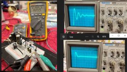
This is the ringing that I observed on a '1541A' transformer with separate and screened secondaries (for all) with schottky bridge into 10R CM resistors and reasonably low value capacitance (1000uF). Both with and without 'snubber'. The snubber circuit is that developed by the 'Quasimodo' guy, values as determined by scope.The tube rectifier (if running on the same transformer) damps transformer ringing and switching noise.
On the veroboard, I added a three-pin header at each of the supplies to 'jump' it in or out of circuit.
Attachments
All the sub-circuit returns are referenced to 127 VAC?
Nope, that's not what I wrote. It's a normal three phase Y system, ground referenced. It's just that I do not have a separate conductor for the safety ground. I only have the neutral conductor, at zero volts, but it carries current back to the transformer room and therefore is not a dedicated safety ground conductor.
Where I come from, the star point for the 'Y' distribution (three phase neutral) is referenced to 0V.
Yes, here as well (I wrote that the neutral conductor is the "return conductor" for all 127V outlets, I thought it was clear; It means a normal wiring, with phase + neutral for each 127V outlet, while 220V outlets are phase + phase, all referenced to earth (down at the transformer room the earthing certainly is done correctly, this is a very well done install for 1960 standards AND was well mantained, although it lacks the aformentioned dedicated safety earth wire at the apartment units)).
I would be very concerned with this.
I am indeed concerned with the lack of safety earth, at the slightest sign of aging/wear I will replace a potentially dangerous appliance such as the washing machine.
All the hot water is gas heated, so there's no danger in the bathrooms.
One possible solution is to re-wire ALL outlets and light fixtures for 220V, and use the neutral wire as the safety earth. This is actually easier than running new wiring all the way back to the transformer room. I am thinking about this.
Last edited:
I see now.
Qualified and with unrestricted license to perform any electrical works (native to my home country).
My advice would be to consult with a local official.
Seems to me, 1.2M earth electrode tied to neutral will solve for all.
As it is, you have reason to be concerned, I'm unfamiliar if you guys have RCD's fitted to sub-circuits etc.
Happy to talk more but seems your best bet is with 'local' - please do so.
All the hot water is gas heated, so there's no danger at the bathroom.
All conductive material pipes should be bonded to the mains earth - at least that is how the more evolved systems have it.
Many times I have reported to cases where the occupants get 'tingles from the tap when brushing their teeth'.
It can be a bit different, but always follows the same principles.
One time I had active and neutral inversed (my mistake at the output to a government owned meter), active hard to 'ground' and the 80A service fuse did not open there was 240V at the chassis of anything that required an earthed chassis (active tied to earth through the MEN at the switchboard).
All to say, its all a bit dodgy, and be mindful.
Last edited:
- Home
- Source & Line
- Digital Line Level
- Building the ultimate NOS DAC using TDA1541A