Hi MGH,
Thanks for your replies [post#734,735 and especially post#744]
> PCM2706 replacement, with the new reclocking setup, jitter is very low. The typical asynchronous two phase reclocking jitter is removed by using the same crystal oscillator for both reclocking and PCM2706 clock signal, and a digital one shot circuit. So what does this mean? USB to I2S converter chip jitter, becomes irrelevant with this setup, since BCK is reclocked by a stable 48 MHz master clock.
Now we have a USB interface that can be connected trough a long USB cable, is bus powered, has isolated differential I2S outputs, very low jitter and at least the same performance as a direct I2S output from a transport. I am now planning to put this USB interface in the octal D-I DAC. However it can also be used separately, but I2S needs to be differential due to the isolation transformers used. I tried the setup with a very short I2S interlink (50 cm) last evening, now sound quality is even slightly better than the CD changer.
> Printed circuit board colour, well last version discussed was one with transparent laquer and (thick) gold plated tracks. When using a coloured laquer, the gold plated tracks are no longer visible. The printed circuit board material itself has a light green colour. The gold plated pad's are soldered anyway. The analog mainboard itself won't be fully visible as it is covered with a annodized aluminum screening plate.
USB audio / mac OSX
Hi adhoc,
Thanks for your reply [post#751]
I have stored images from my original CD's using lossless compression. Apple uses Core Audio, the audio functionality is already integrated in the operating system, so unlike windows it works very fast and efficient. It could only go wrong when processor load remains at maximum. Even with my 450 MHz iMac, processor load during USB audio stream is only around 15%. So there is no problem.
I am not surprized at all that windows can't get a bit perfect stream out of iTunes. That's why I use a mac.
If my iMac wasn't correctly playing back the stored music, I would hear the difference straight away comparing it with my CD changer playing the same track with the original CD. Knowing mac OSX uses Linux as operating system, I am pretty sure the stream is bit perfect.
Thanks EC,
Regarding the USB setup:
"I tried the setup with a very short I2S interlink (50 cm) last evening, now sound quality is even slightly better than the CD changer."
Do you mean the USB module is inserted at the computer USB output and from the USB module, a short I2S cable is connected to the Octal DAC?
Regarding the PCB:
"The gold plated pad's are soldered anyway."
Gold plated pad=trace? Not sure what you mean by pad being soldered. I thought the trace is bonded to the glass epoxy board. Any chance you will also offer a teflon PCB?
Keep up the excellent work.
MGH,
"Solder pads" are where you actually literally attach components to the board. I believe in this case EC means that the solder pads are gold plated, then tinned with solder to enable easy working - stuff that is tinned has a higher affinity (ie more 'sticky') for solder.
"Solder pads" are where you actually literally attach components to the board. I believe in this case EC means that the solder pads are gold plated, then tinned with solder to enable easy working - stuff that is tinned has a higher affinity (ie more 'sticky') for solder.
Hi MGH,
Thanks for your reply [post#763]
> The USB to I2S interface is now placed close to the octal D-I DAC, connected trough a 50cm long differential I2S cable, the USB cable to the mac is 5 meters long.
I did some more direct comparison, I build a I2S switch that allowed me to directly switch between 3 setups:
1) Differential I2S from the CD changer
2) Differential I2S from the USB interface with reclocker
3) Differential I2S form the USB interface without reclocker
So now I could switch between these setup's quickly during listening. I played back the same tracks on both CD-changer and mac, and switched between setups, so a realistic direct comparison could be made.
After many hours of listening and playing lot's of different types of music, setup 1 and 2 produced similar sound quality, setup 3 didn't. It's sound was a bit harsh, sound was not open (sound depth was missing) and the instruments didn't sound realistic.
So even if some people have doubts of the reclocking method used, soundwise it's much better than a clock signal affacted by jitter (phase noise).
But, since I wanted to optimize the USB interface, I started modifying it again. There were some flipflops and synchronous counters used, so I experimented with all chip's that I had laying around, containing flipflops and counters to see if there was a difference in timing and jitter performance that could be used to lower reclock jitter even more.
Strange things happened, a 74HC74 seemed to be very instable and added jitter, even trying other chip's of the same type showed similar problems. Then I used a 74HC164 shiftregister, as it contains flipflops too. This one had much lower added jitter, I also experimented with 74F versions and mixing different speeds. Finally I got a reclocker that had less components and performed even better. When looking at the reclocked BCK on the oscilloscope, it has very low jitter and the two phase jitter is hardly visible with oscilloscope intensity turned up. This means the vast majority of BCK clock cycles has no 2 phase jitter at all.
I added a oscillogram of how the USB audio stream data looks like. It consists of data bursts (packages) every 10ms. So it's quite difficult to obtain a low jitter BCK signal from this, without some form of reclocking or jitter reduction.
> By " the pad's are soldered anyhow" I ment there will be no gold plating visible on the pad's after soldering,
Attachments
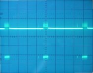
1ms intervals..
Hi all,
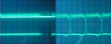
I added another oscillogram of the USB data, intervals are at 1ms intervals (I accidently noted the wrong value in the previous post). At the left a oscillogram of a single USB data packet in more detail, at the right, zoomed-in to view the data pattern. Note USB also uses a differential interface, the oscillogram only shows one of these signals, when both signals are combined in the differential receiver, common noise is cancelled.
There are some interesting articles on the internet about USB and jitter. Basically, with a USB to I2S interface, you need some form of reclocking to get low jitter values.
The USB audio stream doesn't have error correction, bandwith is reserved to ensure other USB devices don't interfere with the USB audio stream. According to information on the internet, when running a USB stream 24 hours a day, one error occurs once every month or so.
Hi all,
I added another oscillogram of the USB data, intervals are at 1ms intervals (I accidently noted the wrong value in the previous post). At the left a oscillogram of a single USB data packet in more detail, at the right, zoomed-in to view the data pattern. Note USB also uses a differential interface, the oscillogram only shows one of these signals, when both signals are combined in the differential receiver, common noise is cancelled.
There are some interesting articles on the internet about USB and jitter. Basically, with a USB to I2S interface, you need some form of reclocking to get low jitter values.
The USB audio stream doesn't have error correction, bandwith is reserved to ensure other USB devices don't interfere with the USB audio stream. According to information on the internet, when running a USB stream 24 hours a day, one error occurs once every month or so.
Attachments
Thanks EC,
Regarding the USB module, why do you have 50cm of I2S cable? Can't you install the USB module on the Octal DAC so you can get as short I2S cable as possible? With a 5 meter USB cable, you really don't need extra 50cm of I2S cable.
Regarding the USB module, why do you have 50cm of I2S cable? Can't you install the USB module on the Octal DAC so you can get as short I2S cable as possible? With a 5 meter USB cable, you really don't need extra 50cm of I2S cable.
USB interface jitter
Hi MGH,
Thanks for your reply [post#768]
I only used this setup for a quick test, I already mentioned planning to integrate the USB interface in the octal D-I DAC [post#761] using very short connections for the differential I2S interface. 5 meter USB cable length is maximum according to specifications.
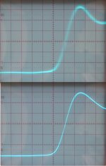
I added a direct comparison between a BCK signal dereived from a USB interface without reclocking (upper oscillogram) and with reclocking (lower oscillogram). The phase noise (jitter) in the upper oscillogram is a common value for a USB interface, without the jitter added trough ground loops (this occurs when you connect the USB outputs directly to a external DAC without isolation).
Oh yes, these are the received BCK signals in the octal D-I DAC, oscilloscope timebase settings are at maximum, .05 uS (50ns) with a X10 timebase setting so each division is about 5nS. Each subdivision represents approx. 1ns
Jitter from a USB interface without reclocking is about 1.5 subdivision so 1.5 X 1ns = 1.5ns or 1500ps! this is without the added ground loop jitter. This value is already to high and sound quality degrades.
Jitter after reclocking depends on the stability of the 48 MHz crystal oscillator, in the prototype setup using bus powered mode, it's already below 200ps, so it probably already meets the 173ps limit, by using a very low jitter oscillator and a very low noise power supply (self powered) jitter values can be lowered, but with self powered mode, special care has to be taken regarding power supply interference (ground loops). With the current setup, the pulse transformers used, have low capacitance between primary and secondary windings (around 5pF).
The 48 MHz crystal clock is divided by 4 (synchronous counter) to obtain 12 MHz clock for the PCM2706, the reclocking frequency relates to BCK as 48,000,000 / 2,822,400 = 17.0068.
Hi MGH,
Thanks for your reply [post#768]
I only used this setup for a quick test, I already mentioned planning to integrate the USB interface in the octal D-I DAC [post#761] using very short connections for the differential I2S interface. 5 meter USB cable length is maximum according to specifications.
I added a direct comparison between a BCK signal dereived from a USB interface without reclocking (upper oscillogram) and with reclocking (lower oscillogram). The phase noise (jitter) in the upper oscillogram is a common value for a USB interface, without the jitter added trough ground loops (this occurs when you connect the USB outputs directly to a external DAC without isolation).
Oh yes, these are the received BCK signals in the octal D-I DAC, oscilloscope timebase settings are at maximum, .05 uS (50ns) with a X10 timebase setting so each division is about 5nS. Each subdivision represents approx. 1ns
Jitter from a USB interface without reclocking is about 1.5 subdivision so 1.5 X 1ns = 1.5ns or 1500ps! this is without the added ground loop jitter. This value is already to high and sound quality degrades.
Jitter after reclocking depends on the stability of the 48 MHz crystal oscillator, in the prototype setup using bus powered mode, it's already below 200ps, so it probably already meets the 173ps limit, by using a very low jitter oscillator and a very low noise power supply (self powered) jitter values can be lowered, but with self powered mode, special care has to be taken regarding power supply interference (ground loops). With the current setup, the pulse transformers used, have low capacitance between primary and secondary windings (around 5pF).
The 48 MHz crystal clock is divided by 4 (synchronous counter) to obtain 12 MHz clock for the PCM2706, the reclocking frequency relates to BCK as 48,000,000 / 2,822,400 = 17.0068.
Attachments
Board Finish Suggestion
Excellent work ecdesigns.
For the board finish I recommend you use is a Gold Flash finish. It is a very thin layer of gold directly over the copper. This makes it very smooth. Very good for SMD and through hole parts.
The gold is so thin that at times it does it look gold at all. But it keeps the copper from tarnishing. The cost to have Gold Flash finish done in China is $0. When you start to solder you start to see the gold colour and it looks nice when you do have some gold parts close to the board.
I recommend you get a quote from the company I use in china info@xufei.com.cn even if you don't use that finish.
Let me know if I can be of any assistance.
Example of Gold Flash finish
An externally hosted image should be here but it was not working when we last tested it.
Brent,
Good idea - my understanding is that for 'typical' gold plating, a layer of nickel has to be laid down first. That can't be good, now, can it?
Good idea - my understanding is that for 'typical' gold plating, a layer of nickel has to be laid down first. That can't be good, now, can it?
hi,
Brent Welke I did not advise U send the gerber file to factory in china to prepare the PCb, otherwise all the market will john's PCb, tey will use very low price to resell. I thought at least must protect john copyright!!!!!
otherwise, john cannot had reasonable profit to support his further project!!!!
John can considerate to print more PCB, resell PCB to share & lower the cost. Pls considerate not to send the file to chine to print.
this is my comment, I will not do any PCB in china I prefer do in taiwan & paid pstage post to hong kong ThenI hand carry back to china to funish.
thx
thomas
bad guys
Hi Thomas,
There are bad guys in any country. One has to consider how safe it is to send intellectual property to someone you haven't built any trust with.
My recommended board manufacturer was because they have a very good price and they delivered my boards to me. Now they are keen to make more of the same boards at the same price or lower. If they are just out to resell the Gerber files they wouldn't be so keen to make more of the same board.
Maybe the second order they are going to rip me off. Those are the chances I take to get a good price. My method is to not send more money then I am willing to loose. Plus I asked for a reference first and checked up on them before sending them money.
Anybody else have a manufacturer they have used and recommend?
~~~~~~~~~~
Flash Gold... Actually I don't know for a fact that nickel is not part of the process. I have not been able to get an accurate answer to that question yet.
Frequency response
Hi Bernhard,
Thanks for your reply [post#770]
Sure I already measured the octal D-I DAC's frequency response using a CD containing both a frequency sweep and using fixed frequencies between 20Hz and 20KHz, but I haven't made a exact frequency response plot yet.
Hi Bernhard,
Thanks for your reply [post#770]
Sure I already measured the octal D-I DAC's frequency response using a CD containing both a frequency sweep and using fixed frequencies between 20Hz and 20KHz, but I haven't made a exact frequency response plot yet.
Octal D-I DAC dimensions
Hi adhoc,
Thanks for your reply [post#771]
The dimensions of the current DAC housing are:
Width, 43cm / 16.93"
Depth, 32.5cm / 12.97"
Height, 12.5cm / 4.92"
Hi adhoc,
Thanks for your reply [post#771]
The dimensions of the current DAC housing are:
Width, 43cm / 16.93"
Depth, 32.5cm / 12.97"
Height, 12.5cm / 4.92"
PCB plating
Hi Brent Welke,
Thanks for your tip [post#772],
> If I am not mistaken, my printed circuit manufacturer already offers a similar plating technique. You noted that when you start to solder, you start to see the gold colour, does this mean it mixes with the soldering tin giving it a gold colour?
> Yes by adapting the solder mask, nice effects could be obtained like the example shown. The printed circuit boards of the octal D-I DAC are placed in a aluminum housing, I plan to annodize the interior of the housing gold coloured, this should give a nice effect as well.
EC,
AFAIK, gold dissolves easily in solder.
However, if too much gold dissolves in the solder, it becomes brittle and solidifies with a dull finish. I think it's also a lot more susceptible to being a cold joint that way too.
So gold isn't all good... I guess. 🙁
AFAIK, gold dissolves easily in solder.
However, if too much gold dissolves in the solder, it becomes brittle and solidifies with a dull finish. I think it's also a lot more susceptible to being a cold joint that way too.
So gold isn't all good... I guess. 🙁
Re: Frequency response
Sorry, forget the frequency response, but did you think about smoothing out the rest of the HF with a transformer ?
-ecdesigns- said:Hi Bernhard,
Thanks for your reply [post#770]
Sure I already measured the octal D-I DAC's frequency response using a CD containing both a frequency sweep and using fixed frequencies between 20Hz and 20KHz, but I haven't made a exact frequency response plot yet.
Sorry, forget the frequency response, but did you think about smoothing out the rest of the HF with a transformer ?
- Home
- Source & Line
- Digital Line Level
- Building the ultimate NOS DAC using TDA1541A