So please tell me why the ac voltage across a trafo with 3,3 Ohm DC resistance is +/-200 mV with +/-2mA AC going through it? Ohms law is not valid any more?.
Ac impedance of the primary of a transformer, within its working frequency and with a non reactive load on the secondary, is NOT varying with frequency. The impedance is the load resistance divided by the ratio between primary and secondary squared!
Concerning the compliance, you might be right, though 🙂
This is because You are using step up transfprmer. 1:16 (Sow. 1496)
3.4ohm x 4mA=0.0136V x 16=0.2176V. Without load and without total loss...
With that in count, this is the pretty much like You said, about 200mV
cheers
AND if it is in Ballanced connection, does not matter with or wo CT conn to gnd, then You will get +6db more... And that is about 400mV p-p like You measure...
Last edited:
This is because You are using step up transfprmer. 1:16 (Sow. 1496)
3.4ohm x 4mA=0.0136V x 16=0.2176V. Without load and without total loss...
With that in count, this is the pretty much like You said, about 200mV
cheers
AND if it is in Ballanced connection, does not matter with or wo CT conn to gnd, then You will get +6db more... And that is about 400mV p-p like You measure...
3.4ohms is the DC resistance, but the trafo isn't a pure resistance when AC is present so your calculation can't apply except for no signal. Its actually about 40R
Balanced will of course give +6db more signal, but I found that grounding the CT reduces the distortion by 66% so I expect injecting current will also do this. These recent posts are more about the effect on distortion of how (& where) to inject the 2ma current than about signal levels.
Last edited:
PLEASE! The 200 mV AC is on the PRIMARY of the trafo. It is measured on the output of the DAC . On the secondary you have 2V AC.This is because You are using step up transfprmer. 1:16 (Sow. 1496)
3.4ohm x 4mA=0.0136V x 16=0.2176V. Without load and without total loss...
With that in count, this is the pretty much like You said, about 200mV
cheers
AND if it is in Ballanced connection, does not matter with or wo CT conn to gnd, then You will get +6db more... And that is about 400mV p-p like You measure...
PLEASE take a look at this side for the calculations on a steuptrafo if you dont believe me:
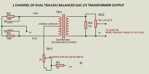
DAC I/V CONVERSION OUTPUT TRANSFORMERS
And look closely where they put the I/V resistor!
PLEASE! The 200 mV AC is on the PRIMARY of the trafo. It is measured on the output of the DAC . On the secondary you have 2V AC.
PLEASE take a look at this side for the calculations on a steuptrafo if you dont believe me:
DAC I/V CONVERSION OUTPUT TRANSFORMERS
And look closely where they put the I/V resistor!
In the case of my Trafo (1495) the secondary will be 3,8 V (actually a bit less with an 1:9+9 trafo)but the calculations I was doing earlier, was for a 1:10 stepup, for easier understanding ..............
Last edited:
So please tell me why the ac voltage across a trafo with 3,3 Ohm DC resistance is +/-200 mV with +/-2mA AC going through it? Ohms law is not valid any more?.
Ac impedance of the primary of a transformer, within its working frequency and with a non reactive load on the secondary, is NOT varying with frequency. The impedance is the load resistance divided by the ratio between primary and secondary squared!
Oh no, not again. Emotional and confident yet incorrect - a bad combination.

Ha!, that Ceglar fellow was switched on, records show that he introduced John to the idea of simdata mode for use with the 1541A.

Last edited:
Oh no, not again. Emotional and confident yet incorrect - a bad combination.
Ha!, that Ceglar fellow was switched on, records show that he introduced John to the idea of simdata mode for use with the 1541A.
Please show why Kolby is incorrect? (I have noticed that you often criticise without showing why you are right and others are wrong)
As far as I can see if the secondary load is 10K, this is reflected to the primary as a 100R assuming a 1:10 ratio.
So this swamps the primary impedance you calculate from the inductance - ie 3H = 188r @10Hz / 188400r @ 10kHz.
If this was not the case surely the frequency response would be terrible, with and especially without, the 100r I/V resistor.
Latest I/V output
I connected the centre tap to +5 through a 1k resistor and 2k preset and adjusted this so the voltage across the 100R I/V resistors was 0.0mv.
I must say the sq is hard to fault - solid and deep bass - any more would be overpowering in my small listening space.
The treble is equally good with no harshness, grain, glare or excessive brightness.
Overall totally untiring to listen to my 'test' CDs (and odd mixture of 'blasts from my past' - Chris Rea 'Road to Hell', Waterboys 'Fishermans Blues', Mussorgsky 'Pictures at an Exhibition', various Handel, Alison Balsom - 'Sound the Trumpet')
I also retired my Martin Logan Aeons as they are about 13years old and need new electrostatic panels at a cost of over £2000. They were replaced warily with a pair of Yamaha NSF51 floor standers which had received excellent Amazon reviews. I was very surprised how tonally similar they are to the Aeons and free from the expected boom boxiness. Imaging isn't as three dimensional but is still excellent. Overall a bargain for £189.
Tomorrow I will connect up the sig gen and scope....
Attachments
Please show why Kolby is incorrect?.
Your question does not make sense in the context of the postings.
I said two things to show Kolby how and why he is incorrect;
1. AC impedance of a transformer varies with frequency.
2. 25mV re datasheet refers to DC compliance.
He refutes the first as being untrue, very emphatically.
Then you ask me to show how and why he is incorrect, despite the fact that this was my whole intention and that I have done just exactly that?.
Again, your question does not make sense.
I made it clear with my response that his position on this reflects a pattern for factual incorrectness presented in an overly over-compensating way, coupled with an inability to be corrected without displaying an overly emotional response.
Would you like an explanation for this as well ?.
Try Google, its free.
Last edited:
Here are my measurements with the Lundahl LL1678:
LL1678
Although it is recommended for moving coil pickup step-up, I used it for DAC transformer. The turms ratio n=1+1:16+16.
Rpri = 4.5 ohm (I measured 5.3 ohm)
Rsec = 375 ohm (I measured 370 ohm)
I measured the inductance by resonance method, connected a 10nF capacitor at the secondary, which gave Fres = 240 Hz. I repeated it by connecting a 100nF capacitor a the primary, which gave 1220 Hz. From these numbers the Lsec = 44H, Lpri = 170mH.
Now we aim for an I/V resistor 10 ohm at the DAC output. We inject 2mA current into the DAC output / I/V resistor junction as it was advised before. Then the voltage swing at the I/V resistor is +/-20mV, well within the +/-25mV compliance from the data sheet.
In reality, we should have added the DC resistance of the primary in series, so we get about 15 ohms.
10 ohm and 170mH gives 10Hz cutoff (T=L/R, T=1/(2*PI*f)).
The 10 ohm can be connected directly at the DAC output, or n^2*R =16*16*10=2.56k at the secondary (2.7k is a convenient value).
The voltage swing at the secondary is +/- 16*20mVp = +/- 320 mVp, about 220 mV RMS.
This calculation does not consider the stray inductance and losses in the transformer. For balanced mode, the only change is you'll get double output voltage, i.e. 440 mV RMS.
AC impedance of a resistor also varies if it is not ideal (inductance).Your question does not make sense in the context of the postings.
I said two things to show Kolby how and why he is incorrect;
1. AC impedance of a transformer varies with frequency.
2. 25mV re datasheet refers to DC compliance.
He refutes the first as being untrue, very emphatically.
Then you ask me to show how and why he is incorrect, despite the fact that this was my whole intention and that I have done just exactly that?.
Again, your question does not make sense.
I made it clear with my response that his position on this reflects a pattern for factual incorrectness presented in an overly over-compensating way, coupled with an inability to be corrected without displaying an overly emotional response.
Would you like an explanation for this as well ?.
Try Google, its free.
My point is that within the working range of the transformer, the variation in AC impedance is insignificant (otherwise its frequency response would be terrible) and the primary impedance is determined by the secondary load resistor. The AC impedance seen by the DAC (and this will be the Riv) is the load resistanc divided by the turns ratio squared.
So a 1:10 ratio trafo with a 10K load resistor will be the same , seen from the DAC as a 100 Ohm resistor as Riv.
And if you measure the two cases, you get the same result: +/- 200mV at the DAC output. The secondary will show +/-2V.
Here are my measurements with the Lundahl LL1678:
LL1678
Although it is recommended for moving coil pickup step-up, I used it for DAC transformer. The turms ratio n=1+1:16+16.
Rpri = 4.5 ohm (I measured 5.3 ohm)
Rsec = 375 ohm (I measured 370 ohm)
I measured the inductance by resonance method, connected a 10nF capacitor at the secondary, which gave Fres = 240 Hz. I repeated it by connecting a 100nF capacitor a the primary, which gave 1220 Hz. From these numbers the Lsec = 44H, Lpri = 170mH.
Now we aim for an I/V resistor 10 ohm at the DAC output. We inject 2mA current into the DAC output / I/V resistor junction as it was advised before. Then the voltage swing at the I/V resistor is +/-20mV, well within the +/-25mV compliance from the data sheet.
In reality, we should have added the DC resistance of the primary in series, so we get about 15 ohms.
10 ohm and 170mH gives 10Hz cutoff (T=L/R, T=1/(2*PI*f)).
The 10 ohm can be connected directly at the DAC output, or n^2*R =16*16*10=2.56k at the secondary (2.7k is a convenient value).
The voltage swing at the secondary is +/- 16*20mVp = +/- 320 mVp, about 220 mV RMS.
This calculation does not consider the stray inductance and losses in the transformer. For balanced mode, the only change is you'll get double output voltage, i.e. 440 mV RMS.
Exactly what I say! I would though recommend , as ECDesign pointed out, that you us a 27K resistor so you get about 100 Ohm as Riv resulting in +/- 200 mV primary and +/- 3,2 V secondary.
Turns out you are not even right WRT output compliance:It is the AC signal current through the DCR which performs the function of IV conversion. AC impedance is the same as DCR for a resistor. AC impedance of a transformer varies with frequency.
So you see what you write cannot be correct.
WRT comment re 25mV and datasheet, this is DC voltage compliance, 25mVDC, and not an vRMS value or anything else.
These are fundamental misunderstandings which have gone unchecked.
HK
What is meant by the DAC output voltage compliance range? | Analog Devices
TDA1541A output voltage compliance
Now I am a bit confused. The data sheet recommends +/-25mV. Even John/ecdesigns say so, e.g.:
https://www.diyaudio.com/forums/digital-line-level/169352-faulty-tda1541a-4.html#post2242071
https://www.diyaudio.com/forums/digital-line-level/79452-building-ultimate-nos-dac-using-tda1541a-361.html#post2480537
https://www.diyaudio.com/forums/digital-line-level/79452-building-ultimate-nos-dac-using-tda1541a-516.html#post3990058
There is some diode at the output that gradually begins conducting, if I understand correctly. I will measure THD vs. I/V resistor and maximum allowed value soon.
Has anyone been able to measure the distortion caused by not meeting the + -25mv specification?
I must say that my dac is sounding better than its ever done since I fed in a current to the CT and adjusted it to 0mv at the dac output pins. I'm sure it also sounds maybe 3db louder which could be due to ALL the dac current flowing into the transformer instead of some going through the I/V resistor? (which are still connected)
However I was looking at the spectrum of a 1Khz sine wave at -10db (as used on previous testing) and there was no 2nd or 3rd harmonics visible and distortion was around as low (.2%) as grounding the CT, but there were two significant spurious non harmonic spikes at about 5.6K and 8.5Khz @-40db which were not present before. I haven't yet investigated what has caused them. They did not seem to be amplitude related and there are no switching spikes on the signal - its completely clean.
Last edited:
Turns out you are not even right WRT output compliance:
What is meant by the DAC output voltage compliance range? | Analog Devices
Must be some mistake here - HK cannot be wrong, he's never wrong - Google supplies all his knowledge and we know how reliable it is.....!
Yes even with +/- 100 mV pr. tda1541 the biggest harmonic (third) is more than 87 dB down (1,2 Khz 0dB digital). 2. harmonic is even lower.Has anyone been able to measure the distortion caused by not meeting the + -25mv specification?
I must say that my dac is sounding better than its ever done since I fed in a current to the CT and adjusted it to 0mv at the dac output pins. I'm sure it also sounds maybe 3db louder which could be due to ALL the dac current flowing into the transformer instead of some going through the I/V resistor? (which are still connected)
However I was looking at the spectrum of a 1Khz sine wave at -10db (as used on previous testing) and there was no 2nd or 3rd harmonics visible and distortion was around as low (.2%) as grounding the CT, but there were two significant spurious non harmonic spikes at about 5.6K and 8.5Khz @-40db which were not present before. I haven't yet investigated what has caused them. They did not seem to be amplitude related and there are no switching spikes on the signal - its completely clean.
If you lower the output (reduce the I/V resistor) you get even better 3. harmonic (< 95 dB) , but John says the perceived sound quality is worse. He actually started out with saying that you had to obey the +/-25 mV compliance and used OPamps as I/V stage to ensure low I/V impednace back in 2007 (!) but found later that the TDA1541a sounded more relaxed and natural with a higher I/V impedance, in spite of the higher 3. harmonic distortion. Still > 87dB att. of the 3. harmonic is a very decent number IMHO.
The THD figure I measure with 0dB digital and 47Kohm on the secondary (equals a 65 Ohm Riv on each TDA1541A) is 0,0063 %! Not too bad and this is @ the output of the DAC/PREamp/volume control.
Yes even with +/- 100 mV pr. tda1541 the biggest harmonic (third) is more than 87 dB down (1,2 Khz 0dB digital). 2. harmonic is even lower.
The THD figure I measure with 0dB digital and 47Kohm on the secondary (equals a 65 Ohm Riv on each TDA1541A) is 0,0063 %! Not too bad and this is @ the output of the DAC/PREamp/volume control.
Yes, that's a good result.
What sig gen are you using and how its supplying the dac?
The software (free or demo) ones I've used via a low cost usb to I2S interface do not have good distortion figures so my results are better than they look as most of the distortion is present in the input signal.
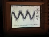
Here are some measurements taken today.
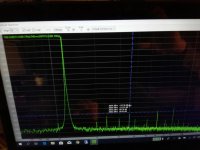
Pic. 1&2
This is with 47Kohm as secondary load, that corresponds to a 145 Ohm between the two TDA1541A and is then a Riv of 77 ohms. The output from the two TDA1541A is +/-400 mV that is +/- 200 mV per TDA1541. The actual Riv is apparently a little higher (100 Ohms).
3. harmonic is 84,44 dB down
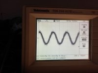
Pic.3&4
This is with 2Kohm as secondary load, corresponding to 6,17 Ohm between the two TDA1541A, The output is now reduced to about +/- 25mV. about +/- 12,5 mV per TDA1541A
3. Harmonic is now higher (-77,17) but this is probably because of the transformers now relatively high DC resistance. Se later.
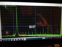
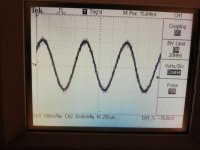
Pic 5&6
R load is now 10Kohm and this is apparently some sort of sweet spot.
R between the two TDA1541A is now about 31 Ohm and voltage +/- 75 mV (+/-37,5 mV each TDA1541A). As can be seen the 3. Harmonic is now < -90 dB.
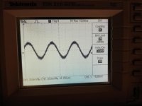
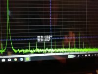
Pic 7&8&9
In all previous measurements, putting the resistor on the secondary side of the trafos measured a little better than placing a Riv across the primary side, but not when using a low value, so the compliance could be met.
I tried to measure with a low Riv (9,25 Ohm between the TDA1541A Riv 4,65) directly on primary side and high load resistor.
Now 3. harmonic was - 82 dB (pic 8)and fell very rapidly as I reduced the digital level to -5 dB (pic 9). In all the other measurements the level of the 3. harmonic was reduced with the same amount as the level.
Pic. 1&2
This is with 47Kohm as secondary load, that corresponds to a 145 Ohm between the two TDA1541A and is then a Riv of 77 ohms. The output from the two TDA1541A is +/-400 mV that is +/- 200 mV per TDA1541. The actual Riv is apparently a little higher (100 Ohms).
3. harmonic is 84,44 dB down
Pic.3&4
This is with 2Kohm as secondary load, corresponding to 6,17 Ohm between the two TDA1541A, The output is now reduced to about +/- 25mV. about +/- 12,5 mV per TDA1541A
3. Harmonic is now higher (-77,17) but this is probably because of the transformers now relatively high DC resistance. Se later.
Pic 5&6
R load is now 10Kohm and this is apparently some sort of sweet spot.
R between the two TDA1541A is now about 31 Ohm and voltage +/- 75 mV (+/-37,5 mV each TDA1541A). As can be seen the 3. Harmonic is now < -90 dB.
Pic 7&8&9
In all previous measurements, putting the resistor on the secondary side of the trafos measured a little better than placing a Riv across the primary side, but not when using a low value, so the compliance could be met.
I tried to measure with a low Riv (9,25 Ohm between the TDA1541A Riv 4,65) directly on primary side and high load resistor.
Now 3. harmonic was - 82 dB (pic 8)and fell very rapidly as I reduced the digital level to -5 dB (pic 9). In all the other measurements the level of the 3. harmonic was reduced with the same amount as the level.
Attachments


I use this :Yes, that's a good result.
What sig gen are you using and how its supplying the dac?
The software (free or demo) ones I've used via a low cost usb to I2S interface do not have good distortion figures so my results are better than they look as most of the distortion is present in the input signal.
Visual Analyser details
It is completely free and have oscilloscope wave generator and FFT analyzer. The results are dependent on your soundcard.
I use USB input to my DAC.
I use this :
Visual Analyser details
It is completely free and have oscilloscope wave generator and FFT analyzer. The results are dependent on your soundcard.
I use USB input to my DAC.
Many thanks. I have installed it and now I just need to read the manual!
My Samsung laptop does not have a very good sound card as the distortion via the headphone output (no line out) is worse than through my dac.
My USB-I2S adaptor uses a PCM 2706 but with only I2S output - no audio or headphone outputs so it should be okay.
I use this as input device. You can use it as output device as well as it has digital out too (s/pdif)
Behringer U-Control UCA222 – Thomann Danmark
- Home
- Source & Line
- Digital Line Level
- Building the ultimate NOS DAC using TDA1541A