Just to close this one out, please see reply on the topic of I2S to PCM board from Ian at #934.
Drive NOS AD1865/62,PCM1704/02/63,TDA1541 from FIFO: Universal I2S-PCM driver board
Drive NOS AD1865/62,PCM1704/02/63,TDA1541 from FIFO: Universal I2S-PCM driver board
Just to close this one out, please see reply on the topic of I2S to PCM board from Ian at #934.
Drive NOS AD1865/62,PCM1704/02/63,TDA1541 from FIFO: Universal I2S-PCM driver board
Yes, Ian has explained why his board works. Datasheets do not cover all possibilities it seems.
I suppose Philips would only have designed and tested the dac chip with the 3 modes provided, and not with any non standard mode so because of this, other modes are not precluded.
I would be caution if I were you since his post proves exactly nothing and there is too much mumbo jambo about sweet sound (like reading descriptions from diyinhk)..
There are lack of any measurements and therefore his assumptions were not proved at all. If I say that something sounds "good" doesn't mean it actually performs good. There are objective methods to perform such tests.
I won't be saying he is wrong since it does not matter, but the approach to the issue is just awful and an actual engineer should provide actual proofs to back up his assumption.
Last edited:
I would be caution if I were you since his post proves exactly nothing and there is too much mumbo jambo about sweet sound (like reading descriptions from diyinhk)..
There are lack of any measurements and therefore his assumptions were not proved at all. If I say that something sounds "good" doesn't mean it actually performs good. There are objective methods to perform such tests.
I won't be saying he is wrong since it does not matter, but the approach to the issue is just awful and an actual engineer should provide actual proofs to back up his assumption.
In science, it is normal for the doubters to try and disprove a theory or claim, usually by trying to replicate it.
Until someone actually proves Ian's method does not work, we can only use the comments of his customers as regards sound quality to support his claim it does work.
This is the only wa,y as his proofs would always be disputed if they do not show that he has followed the datasheet to the letter.
I would be caution if I were you since his post proves exactly nothing and there is too much mumbo jambo about sweet sound (like reading descriptions from diyinhk)..
There are lack of any measurements and therefore his assumptions were not proved at all. If I say that something sounds "good" doesn't mean it actually performs good. There are objective methods to perform such tests.
I won't be saying he is wrong since it does not matter, but the approach to the issue is just awful and an actual engineer should provide actual proofs to back up his assumption.
After re-reading your reply, I have to say that on the one hand you are not saying he is wrong "since it does not matter" - (why?) yet you have done nothing other than quote the datasheet and show what the datasheet predicts.
As regards your comment "...sounds good doesn't mean it measure good". I have for long time, relied on my ears to be the judge. I am not taken in by the latest "state of the art" opamps and dac chips with fantastic specs.
Anyone fooled into believing that specs and measurement guarantees the best quality audio, would have no interest in this thread and the dacs from last century.
If you don't accept Ian's explanation, then prove his board does not work as he says, otherwise your claims carry no more weight than Ian's.
The datasheet explains how you should work with the IC to ensure its proper operation. That is a fact and not some wishful thinking.
Regarding the point that it does not matter - what doesn't matter is whether he is right or I am. It does not really matter for me. The point is to provide actual facts (measurements) of that matter in order to prove your point. Mumbo jumbo about sweet sound is not a proof of anything. It is a marketing strategy for those who are not careful enough to think on their own.
You can take a look at ecdesigns posts. He tells you about sweet sound with his inventions, but he does also provide actual proofs of his claims (measurements). That is exactly how it is supposed to be. You need to back up your claim if you want to violate certain rules (e.g. defined by datasheet).
I have already provided enough information within this thread. The problem is that even if a measurement is right in front of you, telling you that e.g. LSB is lost, you won't believe it. You choose to deny facts on your own and that is your choice.
🙄The datasheet explains how you should work with the IC to ensure its proper operation. That is a fact and not some wishful thinking.
Regarding the point that it does not matter - what doesn't matter is whether he is right or I am. It does not really matter for me. The point is to provide actual facts (measurements) of that matter in order to prove your point. Mumbo jumbo about sweet sound is not a proof of anything. It is a marketing strategy for those who are not careful enough to think on their own.
You can take a look at ecdesigns posts. He tells you about sweet sound with his inventions, but he does also provide actual proofs of his claims (measurements). That is exactly how it is supposed to be. You need to back up your claim if you want to violate certain rules (e.g. defined by datasheet).
I have already provided enough information within this thread. The problem is that even if a measurement is right in front of you, telling you that e.g. LSB is lost, you won't believe it. You choose to deny facts on your own and that is your choice.
Indeed, that is exactly how I feel about it 😉 It is like talking to a wall.
Anyway, I'm done explaining it. However, if required I will always provide some help when I'm available.
I think you got that wrong 🙄Indeed, that is exactly how I feel about it 😉 It is like talking to a wall.
Anyway, I'm done explaining it. However, if required I will always provide some help when I'm available.
DAC TESTER
So, to find out whether the LSB is missing can I make a static dac tester from a 74LV165a parallel in serial out shift register. (x2 & a bit more logic)?
A bank of 16 dil switches specifies the data, pressing a button to take the Load input low loads the settings which are then clocked out by using bck as the clock. Bck is clocking the same data so the dac output should be DC.
WS would need to be supplied but presumably, once the data has been latched into the dac registers, the output will remain at the DC level until the load button has been pressed again.
Is it possible?
It is, it will require some work in general, but it is doable. You need transimpedance amplifier with high amplification though. That is in order to see LSB change.
Personally I would just do an FFT toggling LSB and below LSB.
Personally I would just do an FFT toggling LSB and below LSB.
Guys,
Is this the right thread to discuss Ian's invention?
Doesn't it deserve its own thread???
Cheers,
M.
Is this the right thread to discuss Ian's invention?
Doesn't it deserve its own thread???
Cheers,
M.
Guys,
Is this the right thread to discuss Ian's invention?
Doesn't it deserve its own thread???
Cheers,
M.
We should probably move the discussion of Ian's boards to this thread as this one is really for ECD Designs.
Drive NOS AD1865/62,PCM1704/02/63,TDA1541 from FIFO: Universal I2S-PCM driver board
Guys,
Is this the right thread to discuss Ian's invention?
Doesn't it deserve its own thread???
Cheers,
M.
As the only available I2S to PCM plug and play module, discussion with regard to suitability for specific use with tda1541A seems perfectly at home in 'ultimate tda1541A' thread ?.
Last edited:
As the only available I2S to PCM plug and play module, discussion with regard to suitability for specific use with tda1541A seems perfectly at home in 'ultimate tda1541A' thread ?.
Well, I don't want to repeat myself, but there is the module from JLsounds that supports direct USB2PCM for the TDA1541A....
Well, I don't want to repeat myself, but there is the module from JLsounds that supports direct USB2PCM for the TDA1541A....
Talkaing about I2S to PCM, and not USB to PCM.
Mosaic-DAC
Hi John,
will there be a new revision of the Mosaic-DAC.
What is the present status.
Hi John,
will there be a new revision of the Mosaic-DAC.
What is the present status.
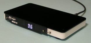
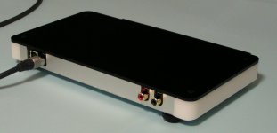
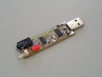
Hi JOSI,
Yes, we completed the new MOS16 and MOS24 DACs that will be presented on our new website soon, together with some other very interesting new products. So keep an eye on our website.
I attached some photographs of the first completed MOS16. The USB socket on the rear is for internal battery charging only.
The MOS DACs can also be connected to USB audio sources while retaining required advantages of Toslink. We designed the UTOS for that, third picture shows the first UTOS prototype.
Mosaic-DAC
Hi John,
will there be a new revision of the Mosaic-DAC.
What is the present status.
Yes, we completed the new MOS16 and MOS24 DACs that will be presented on our new website soon, together with some other very interesting new products. So keep an eye on our website.
I attached some photographs of the first completed MOS16. The USB socket on the rear is for internal battery charging only.
The MOS DACs can also be connected to USB audio sources while retaining required advantages of Toslink. We designed the UTOS for that, third picture shows the first UTOS prototype.
Attachments
Alternatively, my DAC linearity test CD that I mentioned several post ago could be used. It toggles LSB at each bits on three DC levels (bit n-LSB, bit n, bit n+LSB). If LSB is missing, you will see only two DC levels.It is, it will require some work in general, but it is doable. You need transimpedance amplifier with high amplification though. That is in order to see LSB change.
Personally I would just do an FFT toggling LSB and below LSB.
Alternatively, my DAC linearity test CD that I mentioned several post ago could be used. It toggles LSB at each bits on three DC levels (bit n-LSB, bit n, bit n+LSB). If LSB is missing, you will see only two DC levels.
Thanks, that's a better idea.
- Home
- Source & Line
- Digital Line Level
- Building the ultimate NOS DAC using TDA1541A