Ahh yea, I didn't read that part. Well, in general that will work, but if you go into details that LSB offset should be in fact generated by the DAC itself, so the nonlinearity errors of that DAC match with the non-inverting DAC.
Lets be clear on that though - you won't be able to hear any difference on that LSB, but from a technical point of view certain issues might visible on very low-leveled signals.
I quite agree with you there. It was therefore I said it was more of a theoretical (and just for the fun of it) thought. 😛
Well maybe he starts believing he is a dog , if you do it long enough 😛
Alas numbers are not so flexible. The magnitude of the error is 1. However the dac is bipolar so the error is 1 or -1.
Really? I would have thought it was an offset error--. Well maybe I am wrong.Alas numbers are not so flexible. The magnitude of the error is 1. However the dac is bipolar so the error is 1 or -1.
Hi batteryman,
Post #6602 reveals another problem with your setup,
-when the scope is set correctly (channel polarity)-
Data is clocked in at the rising edge (0 -> 1) of BCK. Philips data sheet clearly indicates data has to be clocked in on the -falling edge- of BCK (1 -> 0) see fig. 6. So data changes at the moment it is clocked in.
Propagation delay between BCK and DATA (long wiring, different wire length, different load capacitance) might enable catching the data nano seconds after it changed. That might just be enough, but not very reliable.
So BCK also has to be inverted in order to meet Philips datasheet timing specs.
The mystery around LE remains, LE should go high (0 -> 1) -after- all 16 bits have been clocked in on the falling edge (1 -> 0) of BCK.
Failing to clock in -all- 16 bits will not simply truncate the data word to 15 bits, but will also move all other bits one position so their weight no longer matches.
It is not clear what value ends up in the MSB location. This depends on how the TDA1541A registers are controlled. But it could be that bit 15 of the previous sample end up at the position where MSB should have been.
I suggest to invert both, BCK and LE. This way the bits are clocked in according to the Philips datasheet (fig. 6). LE will go from 0 -> 1 after all 16 bits have been clocked in.
I am still unsure if the negative transient of LE is allowed to occur while data is still being clocked in. This might also be a violation that might cause data corruption.
When inverting LE doesn't work (distortion) you will need extra glue logic to move the negative transient of LE (inverted LE) out of the data window.
Yes I agree it is wrong but yet it sounds okay until there is a peak. (I do have the datasheet)
You'd never suspect a problem if the recording was done at a lower level or the track was of quiet music.
I have tried using half speed mode and also 18 & 20bit settings and none make any difference either to the distortion or to what I can see on the scope.
Post #6602 reveals another problem with your setup,
-when the scope is set correctly (channel polarity)-
Data is clocked in at the rising edge (0 -> 1) of BCK. Philips data sheet clearly indicates data has to be clocked in on the -falling edge- of BCK (1 -> 0) see fig. 6. So data changes at the moment it is clocked in.
Propagation delay between BCK and DATA (long wiring, different wire length, different load capacitance) might enable catching the data nano seconds after it changed. That might just be enough, but not very reliable.
So BCK also has to be inverted in order to meet Philips datasheet timing specs.
The mystery around LE remains, LE should go high (0 -> 1) -after- all 16 bits have been clocked in on the falling edge (1 -> 0) of BCK.
Failing to clock in -all- 16 bits will not simply truncate the data word to 15 bits, but will also move all other bits one position so their weight no longer matches.
It is not clear what value ends up in the MSB location. This depends on how the TDA1541A registers are controlled. But it could be that bit 15 of the previous sample end up at the position where MSB should have been.
I suggest to invert both, BCK and LE. This way the bits are clocked in according to the Philips datasheet (fig. 6). LE will go from 0 -> 1 after all 16 bits have been clocked in.
I am still unsure if the negative transient of LE is allowed to occur while data is still being clocked in. This might also be a violation that might cause data corruption.
When inverting LE doesn't work (distortion) you will need extra glue logic to move the negative transient of LE (inverted LE) out of the data window.
Failing to clock in -all- 16 bits will not simply truncate the data word to 15 bits, but will also move all other bits one position so their weight no longer matches.
It is not clear what value ends up in the MSB location. This depends on how the TDA1541A registers are controlled. But it could be that bit 15 of the previous sample end up at the position where MSB should have been.
Actually it is quite clear. I've been clocking in 14 bits (14 BCK cycles) for TDA1541 and it does just work fine.
I am still unsure if the negative transient of LE is allowed to occur while data is still being clocked in. This might also be a violation that might cause data corruption.
When inverting LE doesn't work (distortion) you will need extra glue logic to move the negative transient of LE (inverted LE) out of the data window.
It isn't allowed. I've been there and I've already had this issue while working on my digital interpolation filter for TDA1540/TDA1541 (up to 384 kHz).
You might want to have a read:
Back to the roots: 14 bits (of TDA1541A) – Audial
So, as far as I understood, simultaneous data protocol is not really “right justified”. Instead, TDA1541A apparently uses LE trailing edge to start loading data into the registers, and LE raising edge to trigger the output, regardless of number of bits previously loaded into the registers.
My tests with my digital interpolation filter did confirm such behavior.
Here is how I see it.Alas numbers are not so flexible. The magnitude of the error is 1. However the dac is bipolar so the error is 1 or -1.
Tda 1541a is actually unipolar it puts out 0 - -4mA. We bias it into being bipolar , by adding exactly half of its max current.
Lets for the sake of simplicity, say it is a 4 bit dac and it can put out 0- -14mA
Digital 0000 is -7 mA from the DAC and each bit is - 1 mA
So if we sum the output from the DAC with + 7 mA we get=
0000 is -7 mA + 7 mA = 0 mA
0001 is -8 ma + 7 mA = -1 mA
1111 is -6 mA + 7 mA = + 1 mA
If we then take the inverted DAC but bias it with 7 mA + 1 lsb current (-1 mA) = 6 mA we get:
0000 inverted = 1111 that is - 6 mA + 6 mA = 0 mA
0001 inverted = 1110 that is - 5 mA + 6 mA = +1 mA
1111 inverted = 0000 that is - 7 mA + 6 mA = - 1 mA
as far as I can see , it only runs into problems @ full scale - 1bit...
Here is how I see it.
Tda 1541a is actually unipolar it puts out 0 - -4mA. We bias it into being bipolar , by adding exactly half of its max current.
Lets for the sake of simplicity, say it is a 4 bit dac and it can put out 0- -14mA
Digital 0000 is -7 mA from the DAC and each bit is - 1 mA
So if we sum the output from the DAC with + 7 mA we get=
0000 is -7 mA + 7 mA = 0 mA
0001 is -8 ma + 7 mA = -1 mA
1111 is -6 mA + 7 mA = + 1 mA
If we then take the inverted DAC but bias it with 7 mA + 1 lsb current (-1 mA) = 6 mA we get:
0000 inverted = 1111 that is - 6 mA + 6 mA = 0 mA
0001 inverted = 1110 that is - 5 mA + 6 mA = +1 mA
1111 inverted = 0000 that is - 7 mA + 6 mA = - 1 mA
as far as I can see , it only runs into problems @ full scale - 1bit...
A couple of errors here. It should be:
0000 is -7 mA + 7 mA = 0 mA
0001 is -6 ma + 7 mA = +1 mA
1111 is -8 mA + 7 mA = - 1 mA
If we then take the inverted DAC but bias it with 7 mA + 1 lsb current (1 mA) = 8 mA we get:
0000 inverted = 1111 that is - 8 mA + 8 mA = 0 mA
0001 inverted = 1110 that is - 9 mA + 8 mA = -1 mA
1111 inverted = 0000 that is - 7 mA + 8 mA = +1 mA
😱


Hi batteryman,
Post #6602 reveals another problem with your setup,
-when the scope is set correctly (channel polarity)-
Data is clocked in at the rising edge (0 -> 1) of BCK. Philips data sheet clearly indicates data has to be clocked in on the -falling edge- of BCK (1 -> 0) see fig. 6. So data changes at the moment it is clocked in.
Propagation delay between BCK and DATA (long wiring, different wire length, different load capacitance) might enable catching the data nano seconds after it changed. That might just be enough, but not very reliable.
So BCK also has to be inverted in order to meet Philips datasheet timing specs.
The mystery around LE remains, LE should go high (0 -> 1) -after- all 16 bits have been clocked in on the falling edge (1 -> 0) of BCK.
Failing to clock in -all- 16 bits will not simply truncate the data word to 15 bits, but will also move all other bits one position so their weight no longer matches.
It is not clear what value ends up in the MSB location. This depends on how the TDA1541A registers are controlled. But it could be that bit 15 of the previous sample end up at the position where MSB should have been.
I suggest to invert both, BCK and LE. This way the bits are clocked in according to the Philips datasheet (fig. 6). LE will go from 0 -> 1 after all 16 bits have been clocked in.
I am still unsure if the negative transient of LE is allowed to occur while data is still being clocked in. This might also be a violation that might cause data corruption.
When inverting LE doesn't work (distortion) you will need extra glue logic to move the negative transient of LE (inverted LE) out of the data window.
I will fit the shorter cat5 cable, hopefully today, and see if the long one has been causing a timing issue, with bck in particular.
I have a 74ACT14 to hand so will try inverting bck first.
A pair of 74HCT7541 octal buffer/drivers is on order if the shorter cable makes a difference.
Hi 3lite,
If this is the case, MSB always ends up at the right position in the input register regardless of the number of bits being clocked in. Then it should work with 14 or 15 bits too and the missing bit 15 simply reduces resolution and should not lead to high level distortion.
Looking at the posted oscillograms and assuming the measurements are correct (correct scope settings) BCK has the wrong polarity.
The oscillogram shows that the data changes right at the moment BCK goes low (data should be fully stable here).
The DAC probably works because of minute delay between data and BCK (BCK changes nanoseconds after data has changed).
This is highly critical timing that could explain the high level distortion. So BCK has to be inverted.
Now we get a new problem as LE goes high on the exact moment BCK goes high (timing violation).
I was afraid of that, when looking at fig. 6 timing diagram this is not allowed.
Anyway, when BCK is inverted, we sample the bits when they have settled completely as it should be.
That leaves the LE timing violation. One way to fix this is to add a one-shot circuit that -only- triggers on the falling edge (1 -> 0) of LE and produces a positive output pulse like this:
-_-_-_-_-_-_-_-_-_-_-_-_-_-_-_-___________ Bit clock (inverted)
__________________________---_________ LE
____________________________--________ One shot output (replaces LE)
Full 16 bit resolution and both, positive and negative edge of the one shot output (that serves as modified LE signal) are now moved out of the data window.
Actually it is quite clear. I've been clocking in 14 bits (14 BCK cycles) for TDA1541 and it does just work fine.
If this is the case, MSB always ends up at the right position in the input register regardless of the number of bits being clocked in. Then it should work with 14 or 15 bits too and the missing bit 15 simply reduces resolution and should not lead to high level distortion.
Looking at the posted oscillograms and assuming the measurements are correct (correct scope settings) BCK has the wrong polarity.
The oscillogram shows that the data changes right at the moment BCK goes low (data should be fully stable here).
The DAC probably works because of minute delay between data and BCK (BCK changes nanoseconds after data has changed).
This is highly critical timing that could explain the high level distortion. So BCK has to be inverted.
Now we get a new problem as LE goes high on the exact moment BCK goes high (timing violation).
It isn't allowed. I've been there and I've already had this issue while working on my digital interpolation filter for TDA1540/TDA1541 (up to 384 kHz).
You might want to have a read:
I was afraid of that, when looking at fig. 6 timing diagram this is not allowed.
Anyway, when BCK is inverted, we sample the bits when they have settled completely as it should be.
That leaves the LE timing violation. One way to fix this is to add a one-shot circuit that -only- triggers on the falling edge (1 -> 0) of LE and produces a positive output pulse like this:
-_-_-_-_-_-_-_-_-_-_-_-_-_-_-_-___________ Bit clock (inverted)
__________________________---_________ LE
____________________________--________ One shot output (replaces LE)
Full 16 bit resolution and both, positive and negative edge of the one shot output (that serves as modified LE signal) are now moved out of the data window.
I will fit the shorter cat5 cable, hopefully today, and see if the long one has been causing a timing issue, with bck in particular.
I have a 74ACT14 to hand so will try inverting bck first.
A pair of 74HCT7541 octal buffer/drivers is on order if the shorter cable makes a difference.
Please check with an oscilloscope that it is actually a I2S signal that you put into Ians converter board..
Please check with an oscilloscope that it is actually a I2S signal that you put into Ians converter board..
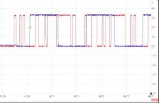
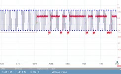
I think the attached screen shots show this to be the case.
Bck = 1.411MHz, WS/LE = 44.1Khz, 32 clock pulses per WS cycle
Master clock from the cd player to Ian's board is 16.9344 rather than the usual 11.289
1st image bck & WS
2nd image D + Ws
3rd, D + bck
Attachments

Last edited:
Difficult to see.. This could be left justified right justified or I2S ...I think the attached screen shots show this to be the case.
Bck = 1.411MHz, WS/LE = 44.1Khz, 32 clock pulses per WS cycle
Master clock from the cd player to Ian's board is 16.9344 rather than the usual 11.289
1st image bck & WS
2nd image D + Ws
3rd, D + bck
But as this is not from a PC, I guess you are unable to only put out left (or right ) data?
It doesn't matter whether it's left, right or I2S for now. The fact is that DATA is clocked on the wrong edge.
Let him fix that with an inverted BCK like me and ecdesigns suggested and we will later fix the LE with some flip-flops to gain extra resolution (1 LSB bit).
Let him fix that with an inverted BCK like me and ecdesigns suggested and we will later fix the LE with some flip-flops to gain extra resolution (1 LSB bit).
Difficult to see.. This could be left justified right justified or I2S ...
But as this is not from a PC, I guess you are unable to only put out left (or right ) data?
No I can't be sure exactly what format it is, but as the audio only distorts on peaks surely it must be I2S. On quiet tracks it never distorts and sounds decent, with good separation and 3D sound stage, clear & smooth treble (maybe a bit too polite) and no aliasing/quantisation noise.
Anything else would not work?
In as much as others have used Ian's converter with the 1541 with no problems, might it not just be a timing issue. eg WS is changing before the MSB has settled, but not every time? (or its more likely that BCK is late rather than WS is early)
if so delaying WS as suggested would work, if the problem is not cured with a shorter cat5 cable. Maybe the new cable + 6 or 12 inverters in series on the WS line is enough. (I have couple of ACT14s)
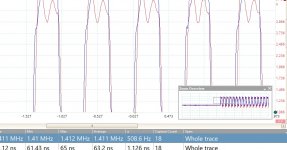
Added screen shot of bck - blue at the converter, red, at the end of 50cm Cat5e cable showing a delay of several ns.
Attachments
Last edited:
Ok. No problem. But it shouldn't be necessary as Ians converter works just fine here (and a lot of other places) with a normal I2S and no additional circuits..It doesn't matter whether it's left, right or I2S for now. The fact is that DATA is clocked on the wrong edge.
Let him fix that with an inverted BCK like me and ecdesigns suggested and we will later fix the LE with some flip-flops to gain extra resolution (1 LSB bit).
Batteryman.
Do you have an USB to I2S board or can you borrow one just to see if it works with that as I2S source? If that works it would rule out Ians board and TDA1541A board as fault source..
Do you have an USB to I2S board or can you borrow one just to see if it works with that as I2S source? If that works it would rule out Ians board and TDA1541A board as fault source..
Most likely Ian's converter never worked fine, but simply some of you were lucky enough not to hear issues.
It would not surprise me at all.
If you have Ian's converter then please take oscillographs of BCK and LE from it when used with TDA1541.
It would not surprise me at all.
If you have Ian's converter then please take oscillographs of BCK and LE from it when used with TDA1541.
Batteryman.
Do you have an USB to I2S board or can you borrow one just to see if it works with that as I2S source? If that works it would rule out Ians board and TDA1541A board as fault source..
I do have one though not used it, and I also have a Marantz CD65 (1541) which I can try if the cable change does nothing.
Most likely Ian's converter never worked fine, but simply some of you were lucky enough not to hear issues.
It would not surprise me at all.
If you have Ian's converter then please take oscillographs of BCK and LE from it when used with TDA1541.
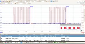
Here they are direct from the output of the converter - same as in post 6653 which were from the dac pcb at the other end of the cat5 cable.
LE is still missing the msb as if its set for 15bits. (I tried the 18bit jumper and sure enough 18 bck are sent but LE then misses the last 3.
The problem seems to be what ECDesgns said - Ian says he is using the falling edge of LE when the dac is using the rising edge. If the rising edge is delayed by 1bck it should work?
Attachments
Last edited:
- Home
- Source & Line
- Digital Line Level
- Building the ultimate NOS DAC using TDA1541A