hi step by step,
I was develop for the output transformer of the DAC, every dac can use
SE to balance or SE outpu stage. two small EI 0.3mmlamination which can run 5ma current.
sec was the I/V transformer of the DAC, before the Op-amp.
than will be the TVC.
will update later.
thx
thomas
I was develop for the output transformer of the DAC, every dac can use
SE to balance or SE outpu stage. two small EI 0.3mmlamination which can run 5ma current.
sec was the I/V transformer of the DAC, before the Op-amp.
than will be the TVC.
will update later.
thx
thomas
Hi Thomas,
Is there a big difference in sound between the S1 and S2? I know you are trying to get us a fair price, but $105 USD is still too high for my budget because I want to get multiple chips. May be a S1 would be a better peformance/dollar choice?
Is there a big difference in sound between the S1 and S2? I know you are trying to get us a fair price, but $105 USD is still too high for my budget because I want to get multiple chips. May be a S1 would be a better peformance/dollar choice?
hi mike mike,
pls go to my thread & discuss for the detail.
If we can groups more orders ( at least 50 pcs) will lower price in USD 90 only.
since this is john's thread. I was not promote for chips. only hope to groups buy for this best chips. Because I need 4 pcs of chips for my coming full parallel 1541a DAC.
sound stage different pls visit back my thread. i suggest U test for one chips first. then considerate to get more. since this chips was very expensive.My project D-1 also only use two 9713 date code double crown only.
It cost JPY 500000 per one, also use two chips. U will understand how expensive of this chips.
for more details that U like ask for me, pls go back to my thread.
thx
thomas
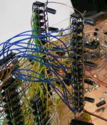
32 X TDA1543 D-I DAC photograph
Hi tubee,
Thanks for your reply [post#626/638]
The OPA627 needs quite some time to settle (10...15 minutes) before reaching optimal performance, perhaps this is also due to the (low) initial bias current in the output stage. I used a matched pair PNP transistor for experimenting, the 2SA1349. Note the OPA627's already had heatsinks installed, just in case. The OPA627 now already starts with the quality normally obtained after 10...15 minutes and then even get's slightly better.
So I thank both you and a333bt for this valuable tip.
You could try the AD823 for I/V conversion some time, maybe it will make a big difference.
Then about the TDA1541A DAC chip's quality.
When combining all information gathered, philips datasheets included, TDA1541A spec's would be as follows:
N2/S2 (double crown) specification: bit 1-7 Edl < 0.5 LSB, bit 8-15 Edl < 1 LSB, bit 16 Edl < 0.75 LSB THD -95dB
N2/S1 (single crown) specification: bit 1-7 Edl < 0.5 LSB, bit 8-15 Edl < 1 LSB, bit 16 Edl < 0.75 LSB THD -97dB
N2 specification: bit 1-16 Edl < 1 LSB
N2/R1 specification: bit 1-16 Edl < 2 LSB
When parallelling DAC's, both noise and distortion can be reduced. Then performance is already very good without using the S1 version.
I am still not sure what the spec's of my TDA1541A DAC chip's are. According to the Philips TDA1541A datasheet it has N2 specifications (<1LSB) because there is no S1 or R1 indication. So if I am correct, the octal D-I DAC uses <1LSB types.
I added a photograph of the 32 X TDA1543 D-I DAC test setup. The 32 TDA1543's draw about 1.29A at 7V.
Attachments
Hi EC,
Looking at your published spec for the S1 and S2, there is no difference except for THD, with S1 having slightly better figure. Isn't that contradictory?
That's some setup for the TDA1543 DAC. I'm surprised you didn't get one of the wires mixed up.
Looking at your published spec for the S1 and S2, there is no difference except for THD, with S1 having slightly better figure. Isn't that contradictory?
That's some setup for the TDA1543 DAC. I'm surprised you didn't get one of the wires mixed up.
Re: 32 X TDA1543 D-I DAC photograph
That is a gorgeous piece of industrial art 🙂
dave
-ecdesigns- said:I added a photograph of the 32 X TDA1543 D-I DAC test setup. The 32 TDA1543's draw about 1.29A at 7V. [/B]
That is a gorgeous piece of industrial art 🙂
dave
A 1541 classification too: (scroll down)
http://www.tnt-audio.com/clinica/tnt1541_e.html
Could be the same but i want to show anyway. The "A" version has <1 LSB accuracy, for better specs get S1 or S2, but i think this is not neccesary within the D-I setup.
Thanks John for opamp info(AD824) Could i use the LT1469 too?
Awesome, that pile of 1543's...... take a good look, somewhere in it must be a rollercoaster turning its rounds.....
Hi MGH,
Thanks for your reply [post#630,642]
> I can't just calculate the octal D-I DAC cost yet, as some more modules need to be added. Only circuit boards and optional housing parts could be supplied, as noted earlier. Most components are relatively cheap, so overall cost for a project like this stays within limits.
> I took the TDA1541A S1 and S2 spec's fom another thread, so I guess I must have mixed them up. As I understand TDA1541A S2 (double crown) has slightly lower THD (better) when compared to the S1 version, rest of the specifications are the same.
But if I personally had to choose between versions, knowing the sound quality the octal D-I DAC already has, a plain TDA1541A is ok for me. If you want to get even better performance, the TDA1541A S1 would be a good trade-off between price and quality.
Since the price of the S2 version is relatively high, one must be sure it's a chip actually meeting the spec's as 8 DAC S2 chip's cost a lot of money. Also the gained sound quality must justify the relatively high price.
> No I didn't mix up any wires, during prototyping I must work very accurate and concentrated, one little mistake can cost many hours of troubleshooting, or can destroy the setup within seconds. When I switched-on the prototype setup worked straight away, I just had to finetune the I/V converters for optimal performance.
It shows that the D-I technique still works accurate with many DAC chip's. The maximum would be 64 (philips format, taps 0...63). It also shows de octal D-I DAC is still a NOS DAC, as the actual sampling rate is not increased. The TDA1543 would not work with 32 or 64 times oversampling.
I added a oscillogram of a 2 KHz sinewave, output by the 32 X TDA1543 D-I DAC without filter, to give an impression of the obtained resolution
Attachments

Reply to Thomas
Report to Post #632
Hi Thomas,
Nice to hear from you. I didn't get mail from you since last of May. The last is that we discussed about transformer coil structure. Do you remind to?
BTW, I send you a mail now, please check. I'll told Mr. Wichai to contact you too.
Regards,
Monsan S.
Report to Post #632
Hi Thomas,
Nice to hear from you. I didn't get mail from you since last of May. The last is that we discussed about transformer coil structure. Do you remind to?
BTW, I send you a mail now, please check. I'll told Mr. Wichai to contact you too.
Regards,
Monsan S.
Thanks EC for the reply.
Yes, I guess you are right. The PCB shouldn't be that expensive unless you go the teflon PCD/silver trace route. It looks like you have nearly completed the chassis. What would you estimate its cost would be?
The Octal D-I DAC is a true balanced design, right? In a balanced design, isn't D-I with 8 chips is equivalent to D-I with 4 chips in a SE design? If you are going to build the Octal DAC and end up using single ended RCA output, what's the benefit of a balanced design? Sorry, I may have asked this before, but I don't recall getting an answer.
EC, did you think about trying your DAC with PCM56 like in the original schematic of that japanese design ?
A good PCM56 with MSB adjust beats every crown chip by > 5 dB on low level signal.
Until today I have tested four S1 from CD players, six S1 NOS and one S2 NOS.
Only one S1 from CD player was good, the rest was good on one channel only or not good at all.
A good PCM56 with MSB adjust beats every crown chip by > 5 dB on low level signal.
Until today I have tested four S1 from CD players, six S1 NOS and one S2 NOS.
Only one S1 from CD player was good, the rest was good on one channel only or not good at all.
Bernard, its about listening, not measuring.😉 😉 Many here like the sound of 1541, and when you do everything in a proper way on this chip, it gives the best. But agreed its not right if specs are not corresponding with S1 or S2 qualification.
Btw, your 304mk2 is one step away of high-end now!
Btw, your 304mk2 is one step away of high-end now!
tubee said:Bernard, its about listening, not measuring.😉 😉 Many here like the sound of 1541, and when you do everything in a proper way on this chip, it gives the best. But agreed its not right if specs are not corresponding with S1 or S2 qualification.
Btw, your 304mk2 is one step away of high-end now!
Hi Tubee
glad you're happy with your 304mkII.
I like the sound of the 1541 too if right implemented
 though prefer the BB because it is easier to select, that's all.
Best: Have a very good crown with SAA7220B
Second: Plain 1541 with SAA7220A
Bad choices:
Mediocre 1541A with 7220B = dominating K5 on low level
As far as I can recall 1541A non os = sounds too warm
The truth is most crowns are not worth the money.
OT:
What can I do with the word clock in / out of a Studer A727 ???
hi monsan,
I received yor email already. Last time we were discuss the winding method of the preamp utput already. its very good. But the ring was quite serious in 100hz ~1Kz aprox +1db, I improve some point & now the Band width can running from 20Hz~37Khz -2db. But we need larger & better core. he ring was remain in +03db, little bit lower already. I will try the nanoamorphous later. this design will use in the coming dac whic use transformer couple for SE & balance output. which was reference to studer A730.
now is testing.
hi berhard,
I was so happy tat U test so any different chips & provide scientific data for me to reference about the design of dac, I guess many diyers will happy too.
this is some information from japan.
pls take a lot that can help U or not.
there is some test information for 1541a, 1541AS1 & 1541AS2 with 6DJ8/ECC88/E188CC tube buffer.
pls take a look.
http://www31.ocn.ne.jp/~kumasiro/TDA1541.htm
http://www31.ocn.ne.jp/~kumasiro/TDA1541AS2-E188CC.htm
http://www31.ocn.ne.jp/~kumasiro/TDA1541AS2-E88CC.htm
hi mike,
do U means the japan circuit about PCM56 was from audionote japan Kondo???
thx
thomas
hi john,
I test many coupling caps for 1541a & the best that I choose was epcos MKP caps.
http://www.epcos.com/web/generator/...epcos_21none_21_20_21_20,protected=false.html
pls try to get some to test.
hope this can help.
thx
thomas
I test many coupling caps for 1541a & the best that I choose was epcos MKP caps.
http://www.epcos.com/web/generator/...epcos_21none_21_20_21_20,protected=false.html
pls try to get some to test.
hope this can help.
thx
thomas
Balanced setup
Hi MGH,
Thanks for your reply [post#652]
> Printed circuit boards now have to be RoHS compliant, so options are limited. If you want a circuit board that can be soldered with both lead-free and leaded soldering tin, the best option to use is gold-plated pad's. Cost is increased 10% by using gold plated pad's.
> The balanced DAC design is mainly used to create a fully DC coupled output without capacitors or transformers as they can affect sound quality. A wire still has the lowest distortion. When the DC coupled output is created, it is applied to a single ended RCA connector.
I did some measurements yesterday on both the 32 X TDA1543 D-I DAC and the 8 X TDA1541A D-I DAC. 0dB sinewave signals resulted in 7.5Vpp for 16 X TDA1543, I/V resistor across op-amp is 202 Ohm, so the full scale DAC current is (7.5 / 202)/16 = 2.3mA, that is the typical full scale current of one TDA1543.
The octal D-I DAC measured 9.5V for 4 X TDA1541A with a 0dB sinewave signal, I/V resistor across op-amp is 590 Ohm, so the full scale current here is (9.5 / 590)/4 = 4mA, again a typical full scale current of the TDA1541A.
So according to these measurements, both D-I DAC setups seem to perform similar to the same amount of parallelled DAC's. The differential op-amp and tube output stage double the output amplitude, as one DAC group has a inverted audio signal (serial data is inverted). So we have (+v1) and (-v2), these are now summed, +v1 goes to the op-amp NON-inverting input, producing +v1 at the output, -v2 enters the op-amp INVERTING input and produces - * (-v2) = +v2 at the output. So the total output amplitude is v1 + v2.
PCM56
Hi Bernhard,
Thanks for your reply [post#653]
The PCM56 cost about 13...16 euro's each, so when it's performance prooves to be equal or better than the double crown TDA1541A during listening sessions, it's a good alternative. The PCM56 uses a resistive ladder network for D/A conversion. Problems occur especcialy at the 011...11 to 100..00 changeover, the datasheet also includes a deglitcher circuit, so problems of this nature are already expected.
The TDA1541A however uses a technique to avoid these errors. The linearity errors are a different aspect. You mentioned the TDA1541A used in a NOS setup produces a sound that's too warm. What type of output circuit was used?
The octal D-I DAC setup is modular, so modules for the PCM56 or other suitable DAC chip's could be designed as well.
decoupling cap's
Hi tube-lover,
Thanks for your reply [post#657]
I already used polypropylene siemens / epcos cap's in both the mosfet cascode amplifier and the earlier sonic resonator crossover filters. But they are used in the signal -path and capacitor quality has a large effect on sound quality. But for TDA1541A they are just used for decoupling the 3 Dynamic Element Matching (DEM) sections (6 MSB's). They must have the same properties as a good (HF) decoupling cap, but leakage current must be low, so both a MKT or MKP will do. The 100nF MKP capacitors have larger dimensions, so connections are longer, counteracting the optimal decoupling characteristics. The TDA1543 uses a similar technique with 5 active dividers and 11 passive dividers, but uses no decoupling cap's. I use small 100nF MKT cap's from BC components (loss factor is 0.015 at 100 KHz).
- Home
- Source & Line
- Digital Line Level
- Building the ultimate NOS DAC using TDA1541A