What is all this absolute rubbish about "eddy current loss" in RCA connectors ??
The currents involved are absolutely miniscule and cause no discernible loss of anything.
This thinking belongs in the snake oil category. I hope you have not succumbed to Bybee
and his bogus products !!!!!!
I am just reporting my personal findings so take it or leave it. The audible loss of resolution was discovered by accident when experimenting with 3.5mm Jack and DIN interlinks.
The Eddy current losses are miniscule indeed but so are the signal levels.
Example:
Reduced volume setting with say 200mVpp and a 16 bit converter.
1 LSB equals 0.2 / 2^16 = 3uV.
It is usual to have around 100 K Ohm load impedance so current for 1 LSB equals 30 pico amperes.
The audibility also depends on the overall resolution of the audio set. I use a novel type of D/A converter (DC-coupled common-rail matrix multibit converter) and high resolution monoblocks for testing. Then the resolution loss of the popular RCA interlinks becomes clearly audible. Best would be soldering the interlinks between DAC and (pre) amplifier, but this would not be very practical.
The effect can be amplified by cascading multiple plug-socket pairs. For example 10 cascaded RCA plug-socket pairs or 10 DIN plug-socket pairs.
The preferred connectors (DIN, mini XLR, 3.5mm Jack) are specifically designed for audio applications and price is low. So I fail to see how this could fall within the snake oil category.
Hi Mike P,
It is best to use a reference for testing the DAC “sound” separately, with studio headphones for example. Your DAC may sound superb on your audio set but how would it sound on other audio sets?
The power supply decoupling caps are in the signal path and thus have direct impact on signal phase cancellation and resulting sound. The caps are basically used as tone control here. The problem with tone control is that it only works optimal for specific music like Jazz, vocal or Classical for example. In the end you would probably prefer to disable this tone control.
One can use a suitable LCR meter for measuring capacitor parameters at different frequencies, say 100Hz, 1 KHz and 10 KHz.
Electrolytic caps offer worst performance (dissipation factor, Q factor, tangent loss angle) and can best be avoided whenever possible. Polarized electrolytic caps are slightly better and film caps are superior.
In this application one can get away with low value decoupling caps so film decoupling caps can be used here.
The TDA1541A has 3 power supplies in the signal path, this adds extra difficulty in obtaining transparent sound.
The voltage regulator properties usually dominate (lowest impedance). So it is best to start with a good voltage regulator before moving on to decoupling capacitor tweaking.
I've now found a combination which sounds just superb in my player!
+5v Elna Cerafine 100uF 25v
-5v Elna Cerafine 100uF 25v
-15v Elna Silmic II 100uF 25v
It is best to use a reference for testing the DAC “sound” separately, with studio headphones for example. Your DAC may sound superb on your audio set but how would it sound on other audio sets?
The power supply decoupling caps are in the signal path and thus have direct impact on signal phase cancellation and resulting sound. The caps are basically used as tone control here. The problem with tone control is that it only works optimal for specific music like Jazz, vocal or Classical for example. In the end you would probably prefer to disable this tone control.
One can use a suitable LCR meter for measuring capacitor parameters at different frequencies, say 100Hz, 1 KHz and 10 KHz.
Electrolytic caps offer worst performance (dissipation factor, Q factor, tangent loss angle) and can best be avoided whenever possible. Polarized electrolytic caps are slightly better and film caps are superior.
In this application one can get away with low value decoupling caps so film decoupling caps can be used here.
The TDA1541A has 3 power supplies in the signal path, this adds extra difficulty in obtaining transparent sound.
The voltage regulator properties usually dominate (lowest impedance). So it is best to start with a good voltage regulator before moving on to decoupling capacitor tweaking.
it's amazing how this guy (mr. Brown) elaborates his answers, I always enjoy reading them;
in my job I must deal with plenty of stupid people around me (it's not my fault they are in such great numbers), so I have to escape quite often this stupidity by reading/studying intelligent, interesting and constructive articles; this is when I realize that just one of these answers contains such a vast background of information when it's elaborated that easily surclass even a whole lifetime of previously mentioned person's creativity/intelligence/conscietization/awareness of information that surrounds him ;
sorry for the offtopic 🙂
Last edited:
Dear -EC- wrote:
Of course, that's my plan. 😎
Dear Luxury,
I hope you are as cool and diplomatic as -EC- when dealing with our stupidity. 😀
M.
Best would be soldering the interlinks between DAC and (pre) amplifier, but this would not be very practical.
Of course, that's my plan. 😎
Dear Luxury,
I hope you are as cool and diplomatic as -EC- when dealing with our stupidity. 😀
M.
Hi Mike P,
It is best to use a reference for testing the DAC “sound” separately, with studio headphones for example. Your DAC may sound superb on your audio set but how would it sound on other audio sets?
The power supply decoupling caps are in the signal path and thus have direct impact on signal phase cancellation and resulting sound. The caps are basically used as tone control here. The problem with tone control is that it only works optimal for specific music like Jazz, vocal or Classical for example. In the end you would probably prefer to disable this tone control.
One can use a suitable LCR meter for measuring capacitor parameters at different frequencies, say 100Hz, 1 KHz and 10 KHz.
Electrolytic caps offer worst performance (dissipation factor, Q factor, tangent loss angle) and can best be avoided whenever possible. Polarized electrolytic caps are slightly better and film caps are superior.
In this application one can get away with low value decoupling caps so film decoupling caps can be used here.
The TDA1541A has 3 power supplies in the signal path, this adds extra difficulty in obtaining transparent sound.
The voltage regulator properties usually dominate (lowest impedance). So it is best to start with a good voltage regulator before moving on to decoupling capacitor tweaking.
I'm certainly writting a stupid thing but my humble expériences to try to setup my tda1541 to the rest of the whole system is in pair with your input here! (I also experiment to try to find an acceptable trade off in relation to the other stupid Staff I have around my DAC... sorry my french, I mean : my stuffs around my DAC)
With 3 independant supplies which are in their outputs a bipolar current follower... I just keeped little by little only one smd film cap of 0.1 uf on the feet of the -16 V (TDA pin 15). So Nothing between the bipolar current followers as said for the two others +/-5V rails.
Unfornatullly it's better with this last ont he -16V than without ! I understand John you uses at least three, one for each pin.
But when playing on the tonal balance game there at least not only the transductor who winn at the most neutral stuff to be founded but also the reservoir caps despite CLCLC before the regulators can be heard (at least I can hear it with one ear like some can see the light with one eye, half a brain is enough some time😀 !)... as you say, inductance, capacitance, tangeant loss, material of lead, loss in the dielectric of this cap, etc (try & error method is as well a help we all is difficult to be measured and modelized )
The second thing is the average middle level of your listening in relation to the dynamic gaps of the notes of music like the time spended to listen the music :
Looking at the Fletcher Munson curve you can see the higher you listen, the tonal balance changes and of course the dynamic gap between the lowest information and the highest one: dynamic (when your reccording is not compresed) becomes smaller (because also most of our speaker are max 105 DB output at 1 meter... and we listened to it at 3 meters. It's different for horned high efficienty speakers owners, but here often I found the mid bass dynamic not on pair with the mid-treble ones.
Also after some minutes of listening, your brain adpats the hearing and you have also the impression on a lower listening level with less dynamic gap but the focused around 3khz zone...for hearing the close dangers 🙂 . those things are important when you read two people have different result with a same environment ! At la revue de l'Audiophile they use to setup always the same db output to test stuffs with a db meter with the same signal iirc... before to beginn any critical listening after a setp up (caps, electronic, supplies, etc) or a different source !
So in our tunning it is better to knwo what is the average listening DB volume for tunning with caps... at least if there are fews, but the CCS of my shunt supplies, I have only 4 caps from the diodes bridges to the TDA 1541 : I mean 4 caps in all for the 3 supplies !
John, I assume reading no answer than you will not test the standalone decoupling on the - 16 V at its TDA feet (pin 15)... so I maybe mistake myself in my conclusions, loose my time, or at least less caps is a tonal balance game yet...
What a pity for me I would have liked to have your testimonial after a little test among your great experience & knowledge on that (the near, close decoupling environment of the tda1541 chip) .
At least it's always a pleasure to read you as says Max. And sorry again if OT as we drive always between your actual TDA1543 design and the oldest TDA154 !
Last edited:
What a pity for me I would have liked to have your testimonial after a little test among your great experience & knowledge on that (the near, close decoupling environment of the tda1541 chip) .
Well, that is the fun and the glory of DIY audio: to be able to tailor the sound of your sistems to your taste/room/mood/musical preferences...etc. 🙂
That's what I like about TDA1543 DACs: they are so simple that every mod is easily evaluated on its sonic effects. I let pass between 2 and 7 days for conclusions.
Last mod: adding 1uF K71-4 military Russian polystyrene caps, after having last week added the 0.25uF caps of the same dielectric (former are axial; later are radial) as DC blocking caps for the output.
I am on the first few hours only... 😎 😎 😱
Yeap, that's true Max! 🙂
As also we always hope than a subjective setup can give to others a little objective improvement in their own system and that we can share these findings... That's all the paradox. It's only objective when it beginns to be able to be measured to be reproduced elswhere and if it improves more than only the system of the owner. There is a hierarchy in improvements though !
One of the most odd is my own system is more limited by the grounding, setup around the dac chip John has been talking about for a while... The more terrible being there are some possible compensations between the things setuped around the chip... sthey upplies, passive parts... if they are only interconnection distorsions so it's quite hearable (horrible also) !
Layout of the pcb must be a solid fundation, many said it but it's even better when you hear it by yourself: ground shematic is more than important despite the relativ low speed FR involved here. Supplies is also more than important but can be wasted by a bad pcb & decoupling... or bad choice of parts also...(while here staying subjective as a compensation for each particular system)... and so on ! At the end all the local impedance, sums of LF & HP with the caps as well make the things hard for valid testimonials.
It's here to try to find the most objective improvements to share.... and it's a ten years thread 🙂 while trying to avoid the false ones or the biggest errors! That was the sense of my asking to John ; if what I heard was objective enough for more than my own setup.
Last edited:
Measurements on the Mosaic
Hi John and kudos on your wonderful efforts.
I was just wondering if there are any measurements available on the new Mosaic DAC.
cheers...
Hi John and kudos on your wonderful efforts.
I was just wondering if there are any measurements available on the new Mosaic DAC.
cheers...
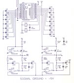
Hi merlin2069er,
I used OP-amps in a dual DC servo circuit (attached picture).
It was used in the final TDA1541A projects SD2 and UD2.
Signal ground is connected to the -5V supply that serves as “ground reference”.
T6 and T7 are current buffers that feed I/V resistors R22 and R23. R20, R21, and C28 ... C30 serve as spectrum shapers (experimental). When spectrum shapers are not required, remove C28 … C30 and short circuit R20 and R21.
U4A and U5A are used as DC servo that keeps DC voltage at the TDA1541A output at zero.
U4B and U5B are used to keep DC voltage on the outputs at -5V. This way there is no DC between -5V “GND reference” and outputs so the coupling cap can be eliminated.
This circuit fully meets TDA1541A output compliance of +25mV and -25mV.
Anyone use op amps on the output of the tda1541?
I used OP-amps in a dual DC servo circuit (attached picture).
It was used in the final TDA1541A projects SD2 and UD2.
Signal ground is connected to the -5V supply that serves as “ground reference”.
T6 and T7 are current buffers that feed I/V resistors R22 and R23. R20, R21, and C28 ... C30 serve as spectrum shapers (experimental). When spectrum shapers are not required, remove C28 … C30 and short circuit R20 and R21.
U4A and U5A are used as DC servo that keeps DC voltage at the TDA1541A output at zero.
U4B and U5B are used to keep DC voltage on the outputs at -5V. This way there is no DC between -5V “GND reference” and outputs so the coupling cap can be eliminated.
This circuit fully meets TDA1541A output compliance of +25mV and -25mV.
Attachments
Hi merlin2069er,
I used OP-amps in a dual DC servo circuit (attached picture).
It was used in the final TDA1541A projects SD2 and UD2.
Signal ground is connected to the -5V supply that serves as “ground reference”.
T6 and T7 are current buffers that feed I/V resistors R22 and R23. R20, R21, and C28 ... C30 serve as spectrum shapers (experimental). When spectrum shapers are not required, remove C28 … C30 and short circuit R20 and R21.
U4A and U5A are used as DC servo that keeps DC voltage at the TDA1541A output at zero.
U4B and U5B are used to keep DC voltage on the outputs at -5V. This way there is no DC between -5V “GND reference” and outputs so the coupling cap can be eliminated.
This circuit fully meets TDA1541A output compliance of +25mV and -25mV.
How about this? Right from the TDA1541 spec sheet.
An externally hosted image should be here but it was not working when we last tested it.
If you have just the output stage for the tda in a pcb, I'd be interested in purchasing it. I'd like to get my red baron up and running.
Hi merlin2069er,
I used OP-amps in a dual DC servo circuit (attached picture).
It was used in the final TDA1541A projects SD2 and UD2.
Signal ground is connected to the -5V supply that serves as “ground reference”.
T6 and T7 are current buffers that feed I/V resistors R22 and R23. R20, R21, and C28 ... C30 serve as spectrum shapers (experimental). When spectrum shapers are not required, remove C28 … C30 and short circuit R20 and R21.
U4A and U5A are used as DC servo that keeps DC voltage at the TDA1541A output at zero.
U4B and U5B are used to keep DC voltage on the outputs at -5V. This way there is no DC between -5V “GND reference” and outputs so the coupling cap can be eliminated.
This circuit fully meets TDA1541A output compliance of +25mV and -25mV.
Hi, I would be interested to know 3 things regarding this "never seen before" implementation 🙂
does it have the standard 2 VRMS output voltage?
what are the power supply voltages used by you for OPA2132 , is it +/- 15V?
can this OPA2132 be substituted for an OPA2134?
thanks
Hi John, thanks for sharing this circuit! Clever servo arrangement.I used OP-amps in a dual DC servo circuit (attached picture).
Ahh, now I see the HF current path, it´s through C29 and C31. Don´t remove those, fellows!
-Alex
Hi merlin 2069er,
When you look at the beginning of this thread at post #5 you will see the twin DAC. Here I used an OP-amp based I/V circuit similar to the one in the Philips datasheet.
The major problems with OP-amps for this application are bandwidth, settling time, and limited bias current in the Op-amp output stage.
Similar to coupling caps, every Op-amp sounds different and no OP-amp will offer transparent sound.
If I had to choose an OP-amp for I/V conversion, soly based on perceived sound quality, I would probably choose the OPA627:
http://www.ti.com/lit/ds/symlink/opa627.pdf
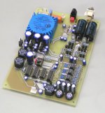
One could attempt to design a discrete OP-amp in order to improve perceived sound quality, I used a discrete OP-amp for I/V conversion in the DI4M DAC (attached picture).
How about this? Right from the TDA1541 spec sheet.
When you look at the beginning of this thread at post #5 you will see the twin DAC. Here I used an OP-amp based I/V circuit similar to the one in the Philips datasheet.
The major problems with OP-amps for this application are bandwidth, settling time, and limited bias current in the Op-amp output stage.
Similar to coupling caps, every Op-amp sounds different and no OP-amp will offer transparent sound.
If I had to choose an OP-amp for I/V conversion, soly based on perceived sound quality, I would probably choose the OPA627:
http://www.ti.com/lit/ds/symlink/opa627.pdf
One could attempt to design a discrete OP-amp in order to improve perceived sound quality, I used a discrete OP-amp for I/V conversion in the DI4M DAC (attached picture).
Attachments
Hi Alexandre,
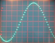
R20, C28, and C29 are part of a spectrum shaper (reactor). It changes the shape of the zero order hold signal into a sawtooh shape.
I attached a picture of the resulting signal (1 KHz)
The sawtooth shape is obtained by charging / discharging C28 / C29 with a constant current from the DAC chip.
The amount of “tilt” can be changed by the value of C28 … C30.
For plain zero order hold output signal simply connect R22 / R23 to the output of U4B and U5B and remove R20, R21, and C28 … C31.
Ahh, now I see the HF current path, it´s through C29 and C31. Don´t remove those, fellows!
R20, C28, and C29 are part of a spectrum shaper (reactor). It changes the shape of the zero order hold signal into a sawtooh shape.
I attached a picture of the resulting signal (1 KHz)
The sawtooth shape is obtained by charging / discharging C28 / C29 with a constant current from the DAC chip.
The amount of “tilt” can be changed by the value of C28 … C30.
For plain zero order hold output signal simply connect R22 / R23 to the output of U4B and U5B and remove R20, R21, and C28 … C31.
Attachments
But John, if you remove C29 and C31 the I/V resistors R22 and R23 would have one terminal connected to the DC servo only, leaving no good HF return path!For plain zero order hold output signal simply connect R22 / R23 to the output of U4B and U5B and remove R20, R21, and C28 … C31.
Last edited:
Hi luxury54,
Output voltage equals 4Vpp / 1.41V rms.
+5 and -15V.
Based on specifications this should be possible.
does it have the standard 2 VRMS output voltage?
Output voltage equals 4Vpp / 1.41V rms.
what are the power supply voltages used by you for OPA2132 , is it +/- 15V?
+5 and -15V.
can this OPA2132 be substituted for an OPA2134?
Based on specifications this should be possible.
Let me expand this... Without those caps the path for the changing current through the I/V resistors now includes the opamp, which it didn´t before. Now, the current will go through the output transistor inside the opamp and out the opamp -V pin... correct?But John, if you remove C29 and C31 the I/V resistors R22 and R23 would have one terminal connected to the DC servo only, leaving no good HF return path!
Instead of "the changing current" I should say the HF components. I do understand (a bit, not yet enough) what I´m saying here... Looking forward to learn more of course, that´s why I care to post this.the changing current
Not sure how relevant it is in practice though, maybe the path through the opamp would be good enough (low enough impedance at said high frequencies) considering that the levels and frequencies of the HF components coming out of the philips R2R dac are not that high, compared to other DACs.
Last edited:
I have been wondering about that reactor circuit since the first time it was mentioned.
Now its time to try it out.
Thanks for sharing it with us John.
My friends just never understand how could a 30 years old Revox B225
sound so natural and real with all its 14bits..... and with some simple tweaks from Ecdesigns.
Now its time to try it out.
Thanks for sharing it with us John.
My friends just never understand how could a 30 years old Revox B225
sound so natural and real with all its 14bits..... and with some simple tweaks from Ecdesigns.
- Home
- Source & Line
- Digital Line Level
- Building the ultimate NOS DAC using TDA1541A