FC with lower value of FM cap works too but at the price of less détails and life in my setup. I agree than in some PS, Pan FC can be too brighty, all dépends on the shematic.
In my setup I talked above, the FC is a reservoir cap for a curent follower (one per rail) and the only cap I populate between the last bipolar and the TDA is a smt small value cap on the -16V rail only after days and days of tests... class Iceramic or PPS (John uses Acrylic smt caps iirc but characteristic are the same as the Panasonic PPS smt caps). I hear a subjective difference between the COG and the PPS and both has to be tried for a subjective listening in relation to the tonal balance of your system.
In some supplies, like 78/79xx a bad ESR cap at the output pin of those OEM regs give better results (try around 220 uF) but it's an old way and at least the voltage rails pins near the TDA needs here a more energic decoupling... I don't know how the Spower reg is made !
Last edited:
In some supplies, like 78/79xx a bad ESR cap at the output pin of those OEM regs give better results (try around 220 uF) but it's an old way and at least the voltage rails pins near the TDA needs here a more energic decoupling... I don't know how the Spower reg is made !
Yes I agree and I found this out myself the hard way. I find the old Elna Durorex caps which have relatively high ESR by modern standards can work very well in these situations.
Here's a link to the Spower regs. I'm using the standard HC version:
Regulators
I've done more listening with the 470uF Oscon SEPC and 0.1uF PPS combination on the +5v pin today and either the caps are 'burning in' or I'm getting more used to the sound, either way it's quite good.
Does the 470 uf stand before the reg as main reservoir cap of the reg or does the 470 uF a last local reservoir bypass cap for the tda after the reg ?
Seems after seing the link that this reg has a ceramic class 2 output cap (give me at home a too brighty sound on the TDA1541 stuffs I have...). The PPS should tame this brightness. But why not uses the reg with Nothing after it ? Try you may be surprised ?!
In your shoes, if too brighty sound, I should try a more soft OSCON SEP (SEPC is harsh, oscillations because too low ESR where it stands in relation to the reg ?) of course BG if you have it. The OSCON SEP has not the little harchness of the old OSCON SP but unfornatully has also not the "boddy" (weight) we love in it ! BG is the better trade off if you need a cap between the output of your reg and the tda pins... with some bypassing with PPS/acrylic (or COG... need a subjective try). An polymer Nichicon LE serie (unluckilly no higher value than 6.5V so for the 5 V rails only could give you an excellent result // wit BG and no smd caps after (no needs with a 470 uf Nichicon LE caps with an ESR of 5 mohms iirc... I tryed it, this is for me the best polymer from Nichicon, better than OSCON but with less weight in the low end...that's why the BG in // is a perfect match !)
In my setup I don't need it and just the small decoupling on the -16V adds more bass and clearness (détails) when populated alone (Nothing between bipolar and +/- 5V pins), the sound is more dynamic, lifely and transparent also in the mediums-highs without harchness or lack of body in the low (accurate tonal balance with the rest of my setup amp+speaker !)
I believe the smd ceramic cap of your Sreg if any is the thing to tame for : you should measure the value or ask the type and value (x7r, x5r ? 0.1 uf ?) to the vendor, maybe suprees it and just play with PPS or COG on the -16 V. At least if the reg doesn't need this output smd near its output pin to avoid oscillation !
But who knows??? without measurement and a serious listening benchmark...
Last edited:
wlowes, are you still using the SMT film caps bypass with the BG's or do you just have the single BG caps now?
I do have 1uf film caps as I was being too lazy to remove. Reading Eldam's comments and recalling that most people have reported that these little BG's prefer to be alone is motivating me to tear this thing apart one last time and remove the film caps and put in the last 0.1uf HiQ caps from my BG stash.
Done!
OK, took the bait and it is good.
I removed the SMT film caps on the 1541a PS pins and replaced with..
-0.1uf BG NX HiQ on the -15v. Turns out this was the last one on hand.
-0.47uf BG NX HiQ on the -5 & +5v pins
These are fresh caps that take 100 hrs to settle. However out of the gate I can tell there is improvement. Just more organic. Less machine. Strings bite. A little more quiet between notes. Slightly more precise stage. Wood has a little more wood and brass.. well more brass.
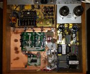
For reference a pic of the bottom and then the entire set on top showing PS's to the 1541a and the tube output. All the digital is below a copper ground plane and dac with its regs is the only thing in its own little copper faraday cage. Nothing as elegant as John's design or execution, but heavily influenced by this great thread.
OK, took the bait and it is good.
I removed the SMT film caps on the 1541a PS pins and replaced with..
-0.1uf BG NX HiQ on the -15v. Turns out this was the last one on hand.
-0.47uf BG NX HiQ on the -5 & +5v pins
These are fresh caps that take 100 hrs to settle. However out of the gate I can tell there is improvement. Just more organic. Less machine. Strings bite. A little more quiet between notes. Slightly more precise stage. Wood has a little more wood and brass.. well more brass.
For reference a pic of the bottom and then the entire set on top showing PS's to the 1541a and the tube output. All the digital is below a copper ground plane and dac with its regs is the only thing in its own little copper faraday cage. Nothing as elegant as John's design or execution, but heavily influenced by this great thread.
Attachments
OK, took the bait and it is good.
I removed the SMT film caps on the 1541a PS pins and replaced with..
-0.1uf BG NX HiQ on the -15v. Turns out this was the last one on hand.
-0.47uf BG NX HiQ on the -5 & +5v pins
These are fresh caps that take 100 hrs to settle. However out of the gate I can tell there is improvement .....
Im a beginner and hope I dont annoy the experts in this thread with my curiosity but Im really excited by these bypass cap effects.
I wonder why the smaller value BG sound better then the 1uF SMT film caps?
Is it the different qualities of the caps or
Is it down to basic circuit design laws with a frequency filtering bandwidth the smaller caps can absorb?
Is there a way to work out what bandwidth the 0.1uF and 0.47uF caps will absorb?
If it is high frequency noise attenuation would that be coming from the power supply or farting back out of the TDA1541a?
Has anyone been able to measure high frequency TDA1541a noise on a scope?
Is there a theoretical high frequency noise predicted from the TDA1541a operation that would then suggest the best value for the PS pin bypass caps?
Would it be worthwhile using eg three different values of caps selected to absorb a wider range of high frequency noise?
Silmic & BG standard would be a far better combo with no bypassing.
Silmic II a little to light for my taste.
Silmic II a little to light for my taste.
Im a beginner and hope I dont annoy the experts in this thread with my curiosity but Im really excited by these bypass cap effects.
I wonder why the smaller value BG sound better then the 1uF SMT film caps?
Is it the different qualities of the caps or
Is it down to basic circuit design laws with a frequency filtering bandwidth the smaller caps can absorb?
Is there a way to work out what bandwidth the 0.1uF and 0.47uF caps will absorb?
If it is high frequency noise attenuation would that be coming from the power supply or farting back out of the TDA1541a?
Has anyone been able to measure high frequency TDA1541a noise on a scope?
Is there a theoretical high frequency noise predicted from the TDA1541a operation that would then suggest the best value for the PS pin bypass caps?
Would it be worthwhile using eg three different values of caps selected to absorb a wider range of high frequency noise?
Kazap
I think you ask the right questions, and I look forward to seeing what others with more experience might comment. It is a subject that has been hotly debated and discussed in the past. I don't want to spark a caps do or don't have an effect debate in John's thread. If you search BG their marketing blurb in the day claimed..
a noise level of –174kb by measurement with distortion meter CLT-1 EX... 40-50db below Oscon. Their marketing hype is preserved at partsconnextion link
below. rpt 112 claims 3rd harmonic distortion way below org polymer and effective operation from 10mhz to 1ghz. To me they just sound better and difference is not subtle.
http://www.partsconnexion.com/t/resources/blackgate/blackgate_index.pdf
Last edited:
And if a shunt reg, it wil be even better removing the 0.47 uF to let the +/- 5V with NOTHING ! But of course with the Distinction 1541 pcb of the photograph the main reservoir cap ground are seing pin 14 impedance first (DGND) instead to have a short grounding near pin 5 as the smt are on the same PCB (it's cheese or cake but not twice !). Again to do short: you must avoid the grounding vias of the main radial reservoir caps on the "bad" (my own though) Distinction-1541 if you populate the smt decoupling pads ! of course tou must wire the grounding of the main supply on pin 5 ... and as the picture I see above has 3 caps glued on the edge of the tda Distinction pcb... the experiment is biased and not in pair with that I wrote. But it's interressant a subjective better result works...
Next experiment should be to try 0.02 uF then 0.1 uF alone on the -16V instead the BG N 0.1 uF... and try with PPS and COG to benchmark both like I did !
I surmise the internal ground of the TDA to work better like that just with a small near decoupling on pin 15 only (-15V) only... if the pcb and its grounding is good ! And if all the 3 rails are feeded with current follower and independant PS.
John, despite all the measurements, did you try my way ? It is maybe just a luck I had in relation to my whole system ! I was very interressed by what you wrote with the very small smt value you choosed yourself 10 nF iirc... but it was a bypass... I find myself in my particular PS setup that 0.02 to 0.1 uF only on the 15 pin works best (dépends on the PS shematic of course). I will be hapy to have your subjective listening on your SOTA PCB and output stage.
I would be happy to have your subjective try and input after it...
@ Kazap, the first requirement is to have a wide band width PS, not Noisy and if possible with a low output impedance. What I am talking about with decoupling caps is with 3 independant supply for the TDA, with 3 Rcore traffo... So the decoupling I'm talking about is in this environment. I was surprised than removing the 33 uF BG N at -16v local decoupling and BG on the -/+5V local decoupling gived a far better result with those supplies... with a fast PS at least, I surmise the PPS or COG alone on the pin 15 (-16v) to give the best result if the grounding is well made (pin 5 agnd not touching a ground near pin 1 to 4... but seing pin 14 DGND...elsewhere !)....
Last edited:
It would be interressant to have a benchmark at local decoupling between the 0.1 uF BG NX and a 0.1 smt PPS.... but saying there are before 3 main BG caps (values ?) at the edge of the PCB... and that the red one seems to be a BG N (value?)...
If removing the two blue BG NX at the left and just leave the -16V BG NX : it would be also interresting to make two try as the two leads give different subjective listening with the grounding : bipolar but has a sense as said P. Rodgic here at DIYAUDIO long time ago ! I can hear it in my system ! I also tried with the 3 voltages all the possibilities with BG N and NX with ground... I prefer the longest or marked lead on the polarized rail (so shortest lead on ground).
Sorry John, I remember you talked in fact of a 1 nF value only on the 3 voltage rails on the TDA1541 pins (the closest possible as you showed). I remember as well you rated better COG ceramic than class II ceramic : my subjective tries are on pair with that... : class 2 is shiny at home but not class 1 COG despite the huger inductance (bigger casing of ceramic class I than littlier X7R class 2 )
Last edited:
I've now found a combination which sounds just superb in my player!
+5v Elna Cerafine 100uF 25v
-5v Elna Cerafine 100uF 25v
-15v Elna Silmic II 100uF 25v
This combination sounds stunningly good to me. The Cerafines when used on the 5v supplies give a much more 'open' energetic and detailed sound than the Silmics without sounding shrill or overly bright. Retaining the Silmic on the -15v line and for the op amp supplies seems to help keep a certain smoothness to the sound.
If your system is very bright and forward Silmic on all supplies may be better as they are wonderfully smooth and natural. Similarly if your system is too dull and shut-in then try Cerafine all round.
The -16 V pin is the most sensible of the 3 voltage rails when it comes to setup the "sound" in relation to the whole system. I always beginn with this rail when I try many setup !
Is there somewhere please in this thread a shematic on how "to remove" -10 V from the -15V rail to feed the - 5 V rail when a single supply is made for the two negative rails?
Remember John talked about that before but can not find it again !
Is there somewhere please in this thread a shematic on how "to remove" -10 V from the -15V rail to feed the - 5 V rail when a single supply is made for the two negative rails?
Remember John talked about that before but can not find it again !
In my CD player the -5v supply is cascaded from the -15v supply. By that I mean there is a -15v voltage regulator and then on the output of this there is a -5v regulator. Is that what you meant? I guess maybe it could be done with a string of zener diodes?
I don't remember exactly, it was not an OEM reg which is in serie with its input from the -15V to make an other rail but more Something in // fron a common negative rail !
I would like to try it with an independant supply for the -15V & -5 V and an other one for the +5V, so two traffo & diodes bridge instead 3 !... to understand more the relation of the grounding and decoupling between the -15V & -5V.
Each time I find than the local decoupling of the - 5V has less impact on the -15V. Each time I remove a local decoupling on the -5V the result is better, the opposite: same value than the -15V on the -5V and the -15V with no decoupling is far worst ! But the relation between -15V local decoupling and +5V has more interactions on the sound... and definitly better without any thing on the -5 V (I tried 10 nF to 2 uF on the +5V with the same range on the -16V... a lot of time... but always a great pleasure ! Hobby🙂 )
Little by little after tried a lot of ancient and modern polymer, electrolytic cap, and smd, Black Gate gived the best subjective quality... but finally I find a setup even better without any Blackgate in my setup with the setup I testimonied above : FC cap feeding a current follower discrete darlington (P. Rogic design) and just one smd cap on the -15 V (Nothing between the other supply and the pins of th e-5v & + 5V).
So I gave up all more huger local reservoir cap of 100 uF and more between my PS and the TDA but this standalone smt cap on the -16V pin of the TDA1541. 0.1 uF works fine (PPS is warmer than COG : different tonal balance). before the -16V PS the big reservoir cap of the -16V rail is a FC// with a a more little FM. FC alone before the - 5 & + 5V... three rails are independant with their own traffo & rectifiers !
But I'm asking myself if there is not Something to make merging the -5 v and -16V only... there is Something I'm curious around the grounding here... some old player had a smt caps iirc bettween the ground of the -16V rail and the - 5 V... or Something like that I don't understand ! And I'm asking myself is the goog setup I have with just a standalone smt cap on the -15v feet of the TDA is working like that by the internal grounding of this chip with the -5V... or else ! Just curiosity because I didn't find a better setup by now and I'm happy to save my BG N caps for some other supply !🙂
Last edited:
It would be interressant to have a benchmark at local decoupling between the 0.1 uF BG NX and a 0.1 smt PPS.... but saying there are before 3 main BG caps (values ?) at the edge of the PCB... and that the red one seems to be a BG N (value?)...
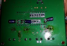
The 2 big caps after the shunt are 16v BG FK 470uf on the +-5v supplies. These were a nice sound add at the time I still had the Oscons on the pcb. They are soldered, so sorry to disappoint, but unlikely to mess with them. The larger red cap on the -15v rail is a pair of BG NX 1000 wired in Super E style. I will try these in and out as I don't recall they made an improvement and they could be reused elsewhere.
I will say the current setup is sounding pretty good.. much better than with the smt film. Everything way more natural with improved sound stage. Every instrument sounds real and stands by itself instead of getting mushed into the others. Thanks for sharing your experience.
It seems all depend on the PS shematic.
Playing with the 3 rails around the TDA1541 seems to be a good way to setup the final sounding result. Strange than at home BG is better without it...
Analog output stage of course has its role in it ...
You should try removing below your pcb the two local BG N of the -/+ 5V and just keeping the local 0.1 uF BG NX on the -16V (with trying in the two sense for leads... or try a super E with again in local with two 0.1 uF at its feet... I believe there is a mark on the plastic bottom of the BG NX to recognize the longest lead).
but with those two FK and teh two big BG N, my setup can not be tryed by you. Hope John would have time to give a chance to my setup... story to know where I am on the bridge in relation to him sota oldest 1541 DAC ! (I mean with this story of local decoupling and if it helps as all of us have different PS ! )
Last edited:
I would like to try it with an independant supply for the -15V & -5 V and an other one for the +5V, so two traffo & diodes bridge instead 3 !... to understand more the relation of the grounding and decoupling between the -15V & -5V.
Easy to read right passed it but I think there is something in this.
A -10V supply if referenced correctly would work, and keep the voltage between these two pins (supposedly critical but who knows) constant.
Anyway, gotta fly!.
LH/S
The 2 big caps after the shunt are 16v BG FK 470uf on the +-5v supplies. These were a nice sound add at the time I still had the Oscons on the pcb. They are soldered, so sorry to disappoint, but unlikely to mess with them. The larger red cap on the -15v rail is a pair of BG NX 1000 wired in Super E style. I will try these in and out as I don't recall they made an improvement and they could be reused elsewhere.
I will say the current setup is sounding pretty good.. much better than with the smt film. Everything way more natural with improved sound stage. Every instrument sounds real and stands by itself instead of getting mushed into the others. Thanks for sharing your experience.
Dear Wolves,
Which PS are you using?.
Ludwig
I am using self built PS(s) based on many influences including this thread. Each is a separate PS consisting generally of small Hammond 229 style transformer (Low primary to secondary coupling and low EMF radiation), super soft recovery diodes, clclclclc filtering. A lot of parallel Panasonic FM caps. Shunt regs from Oliver's Red Baron project. I kind of started down the Red Baron path but deviated. Reading from John's advice about many levels of filtering (I think he suggests 9 deep) I tried it both ways, Oliver's massively paralleled caps vs John's clc approach and far preferred the latter. experimented with crc with different resistor values vs clc and far preferred clc with high current chokes. All of this by ear, not scope but seems to make sense that highly filtered supplies work well with this chip. Same on all the digital front end supplies. Clock supply is particularly important. There I used a TPA4700 based reg by Ian Canada. The BG HiQ caps worked very well around the clocks.
I am using self built PS(s) based on many influences including this thread. Each is a separate PS consisting generally of small Hammond 229 style transformer (Low primary to secondary coupling and low EMF radiation), super soft recovery diodes, clclclclc filtering. A lot of parallel Panasonic FM caps. Shunt regs from Oliver's Red Baron project. I kind of started down the Red Baron path but deviated. Reading from John's advice about many levels of filtering (I think he suggests 9 deep) I tried it both ways, Oliver's massively paralleled caps vs John's clc approach and far preferred the latter. experimented with crc with different resistor values vs clc and far preferred clc with high current chokes. All of this by ear, not scope but seems to make sense that highly filtered supplies work well with this chip. Same on all the digital front end supplies. Clock supply is particularly important. There I used a TPA4700 based reg by Ian Canada. The BG HiQ caps worked very well around the clocks.
Hi Joshua_G
Here is the mechanism:
Modulated RF carrier frequencies, for example SMPS switching frequency (carrier) with (LF) noise modulated on it -> demodulation -> interference within the audio spectrum that is added to the audio signal as distortion.
Digital audio generates and uses RF energy (MCK, BCK, DATA, WS, and so on) that creates modulated carriers as well, this makes matters even worse.
The interlinks act as RF filters and because every interlink has -unique- RF filter properties, each interlink will sound different as it creates a unique distortion spectrum after demodulation of the modulated carrier waves riding on it.
So we have an inaudible modulated carrier frequency that gets filtered by the interlink and then demodulated by connected circuits. After demodulation of these filtered carrier frequencies we end up with interference that can fall within the audio spectrum and thus can be audible.
So yes there is an audible and measurable difference but no, it is not caused by “special” copper.
My listening experience tells me something different. Some different copper wires sound differently.
Here is the mechanism:
Modulated RF carrier frequencies, for example SMPS switching frequency (carrier) with (LF) noise modulated on it -> demodulation -> interference within the audio spectrum that is added to the audio signal as distortion.
Digital audio generates and uses RF energy (MCK, BCK, DATA, WS, and so on) that creates modulated carriers as well, this makes matters even worse.
The interlinks act as RF filters and because every interlink has -unique- RF filter properties, each interlink will sound different as it creates a unique distortion spectrum after demodulation of the modulated carrier waves riding on it.
So we have an inaudible modulated carrier frequency that gets filtered by the interlink and then demodulated by connected circuits. After demodulation of these filtered carrier frequencies we end up with interference that can fall within the audio spectrum and thus can be audible.
So yes there is an audible and measurable difference but no, it is not caused by “special” copper.
- Home
- Source & Line
- Digital Line Level
- Building the ultimate NOS DAC using TDA1541A