re post #5398 above, I'm quite confused about the description of the -15 volt decoupling caps (and it's bypass ??) ground tracks description.
... with the main cap tied at the digital ground near pin 14 and the little smt decoupling cap tied near pin 5 (direct path).
From my limited understanding, the -15 volt supply 'on board bypass caps' (all of them) should be connected to analogue ground and not digital ground - I would imagine the same thing would also apply to the 1541 'non-A' version
Does Ryan's pcb have this one bypass cap attached to pin 14 and another cap attached to pin 5?
-----------------------
If the ground plane that's attached to pin 14 is presenting a problem for your unit, simply cut the track and attach the 'plane to either the pin 5 ground or maybe, any other ground point that 'does the job' - just try it and see.
James,
Thank you for this input,
your knowledge and great diy experience with the TDA1541 is always greatly appreciated from beginners like I still am 🙂.
To answer your question : no, the -15v smt // decoupling cap is tied with a standalone at the bottom path side to pin 5, this last pin 5 is shared with the digital ground at the upper side.
Main -15 v decoupling radial cap is directly on the digital both upper & botom ground (the + lead of the cap), so the main cap "see" directly the close pin 14 while the smt little // cap see firstly the pin 5 then the pin 14 after through a longer way on the common continuous upper plane. Ryan says it's better like that (because harmonics of the squarewaves, and pushed some Pedja Rogic and Henk from Philips.... but as I have a doubt, so I ask here !
Montgomery at DIYAUDIO from March 2015 only🙄,
Maybe you readed not the good thread, maybe you want to change the true story ? WE were almost 10 curent contributors to this board and fixed some issues than Ryan drawed on the base of a first previous design with John inputs. Mostly some improvements like the uf-l are a direct asking of mine clearly. It was clearly a common work of many people, even if Ryan share him first design and redraw it with our inputs ! Even some great members like Marce fellow briefly shared ! I have also many PM to me from asking to great members and answers I shared, sometimes anonymously at their whisch !
So no, sorry, he developped not the whole thing alone but drawed and when people like I asked to the gerber files we just had as answer "All is under controll now" (=no).
Great contribution of him has not to be forgoten, and Ryan is a friend of mine yet, but here I just want to ask John if WE made an error on the ground layout ... and it's not your business !
Mostly this is not important here, it's John's thread not the place of the austalians buddies, you said yourself just having heared the first batch only and not the Distinction1541 board We made (logistic was by Ryan !)and I'm sure the advise John will give to us will be greatly apprecied !
What is surprising me is you talk of Ryan but in any case you say maybe I'm wrong with what I ask ! (and maybe I am wrong...but have the courage to ask!)
John please, any idea about what I asked please 🙂. And I'm very sorry for this off topic, sometimes false words must be corrected !
Thank you for this input,
your knowledge and great diy experience with the TDA1541 is always greatly appreciated from beginners like I still am 🙂.
To answer your question : no, the -15v smt // decoupling cap is tied with a standalone at the bottom path side to pin 5, this last pin 5 is shared with the digital ground at the upper side.
Main -15 v decoupling radial cap is directly on the digital both upper & botom ground (the + lead of the cap), so the main cap "see" directly the close pin 14 while the smt little // cap see firstly the pin 5 then the pin 14 after through a longer way on the common continuous upper plane. Ryan says it's better like that (because harmonics of the squarewaves, and pushed some Pedja Rogic and Henk from Philips.... but as I have a doubt, so I ask here !
Eldamo, i personally connot see any of your input in ryans board, i heard his previous one which was excellent. He made the changes himself, before bringing out the current board. I dont think this warrants you saying that ''we developed it'', when clearly ryan j was the only one who made it.
Montgomery at DIYAUDIO from March 2015 only🙄,
Maybe you readed not the good thread, maybe you want to change the true story ? WE were almost 10 curent contributors to this board and fixed some issues than Ryan drawed on the base of a first previous design with John inputs. Mostly some improvements like the uf-l are a direct asking of mine clearly. It was clearly a common work of many people, even if Ryan share him first design and redraw it with our inputs ! Even some great members like Marce fellow briefly shared ! I have also many PM to me from asking to great members and answers I shared, sometimes anonymously at their whisch !
So no, sorry, he developped not the whole thing alone but drawed and when people like I asked to the gerber files we just had as answer "All is under controll now" (=no).
Great contribution of him has not to be forgoten, and Ryan is a friend of mine yet, but here I just want to ask John if WE made an error on the ground layout ... and it's not your business !
Mostly this is not important here, it's John's thread not the place of the austalians buddies, you said yourself just having heared the first batch only and not the Distinction1541 board We made (logistic was by Ryan !)and I'm sure the advise John will give to us will be greatly apprecied !
What is surprising me is you talk of Ryan but in any case you say maybe I'm wrong with what I ask ! (and maybe I am wrong...but have the courage to ask!)
John please, any idea about what I asked please 🙂. And I'm very sorry for this off topic, sometimes false words must be corrected !
Last edited:
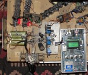
I'm having great fun modifying my new DUAL-MONO DACs, based on the humble TDA1543... 😀
The SD card player coupled DAC is now playing sweet music in the "direct out" (passive IV; removed the transimpedance amp) and with attenuators for the I2S signals (including RR and LL DATA).
Removing the active circuits caused only a little lower bass output, which was excessive anyway, so I don't miss it all, and "all the rest" improved. Terribly energetic this DAC is, yet much more refined than its predecesor.
Next experiments are: using separate quality voltage regulation for each subunit; and since Vout is plenty, using only Rout for each mono wing.
In fact, I am thinking about trying the passive route for my beloved "scrambler-interpolator DI4M DAC", using 4 honeycomb I/V resistors (and 4 V references) and going for the ballanced output direct coupled to my TVC. The perfect match of the VDCout in each fase should cancel at the transformer and spare it...or use output caps, no worry...
After all this I have a request for John:
In the past, you have recommended several combinations for the I2S attenuators and I would love to read the philosophy behind, since I only grasped the surface of it. From my experiences with various sources, I decided to keep the series 3K3 resistors and use variable resistor pots for the G and V+ resistors. That way I can adapt and get the DAC chip to "lock" the signal, with different resistance combinations, though from time to time a get in troubles...maybe for low voltage sources it is better to use lower series resistance...
From my measurements, High state is (+)1200mV and Low state would be something under (+)800mv, for a signal amplitude of (+)400mV, pk to pk. Correct me if I am wrong.
Can you comment about the variables to consider and choose the optimal resistor combination and achieve perfect function?
I would be (I am) very grateful. 🙂
Best wishes.
M.
-EC's- greatest fan. 😎
Attachments
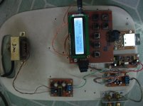
Where did you get the SD player from?I'm having great fun modifying my new DUAL-MONO DACs, based on the humble TDA1543... 😀
The SD card player coupled DAC is now playing sweet music in the "direct out" (passive IV; removed the transimpedance amp) and with attenuators for the I2S signals (including RR and LL DATA).
Removing the active circuits caused only a little lower bass output, which was excessive anyway, so I don't miss it all, and "all the rest" improved. Terribly energetic this DAC is, yet much more refined than its predecesor.
Next experiments are: using separate quality voltage regulation for each subunit; and since Vout is plenty, using only Rout for each mono wing.
In fact, I am thinking about trying the passive route for my beloved "scrambler-interpolator DI4M DAC", using 4 honeycomb I/V resistors (and 4 V references) and going for the ballanced output direct coupled to my TVC. The perfect match of the VDCout in each fase should cancel at the transformer and spare it...or use output caps, no worry...
After all this I have a request for John:
In the past, you have recommended several combinations for the I2S attenuators and I would love to read the philosophy behind, since I only grasped the surface of it. From my experiences with various sources, I decided to keep the series 3K3 resistors and use variable resistor pots for the G and V+ resistors. That way I can adapt and get the DAC chip to "lock" the signal, with different resistance combinations, though from time to time a get in troubles...maybe for low voltage sources it is better to use lower series resistance...
From my measurements, High state is (+)1200mV and Low state would be something under (+)800mv, for a signal amplitude of (+)400mV, pk to pk. Correct me if I am wrong.
Can you comment about the variables to consider and choose the optimal resistor combination and achieve perfect function?
I would be (I am) very grateful. 🙂
Best wishes.
M.
-EC's- greatest fan. 😎
Koldby
Google QA 550 SD card player.
Here a discussion:
http://www.diyaudio.com/forums/digital-source/150199-qa-550-sd-card-16-44-1-wav-transport.html
Cheers,
M.
Here a discussion:
http://www.diyaudio.com/forums/digital-source/150199-qa-550-sd-card-16-44-1-wav-transport.html
Cheers,
M.
Cleaner and tighter sound.
The link above shows many upgrades (I will begin mine) that shall improve it further. 😎
Cheers,
M.
The link above shows many upgrades (I will begin mine) that shall improve it further. 😎
Cheers,
M.
Cleaner and tighter sound.
The link above shows many upgrades (I will begin mine) that shall improve it further. 😎
Cheers,
M.
What kind upgrade do you have in mind ?
I build similiar player from koon (member of diyaudio)
Attachments
I was thinking about improved Vregs for the main chip and the clock, and also about adding buffers for I2S.
Maybe someone can recommend the best buffers: here I have 74HC125 at least.
Best wishes,
M.
Maybe someone can recommend the best buffers: here I have 74HC125 at least.
Best wishes,
M.
Thank you. I'll try it ASAP.
Edit: I found an old comment from -EC- where he states that this buffer could be too slow and could result in added jitter. Will need faster buffer.
Edit: I found an old comment from -EC- where he states that this buffer could be too slow and could result in added jitter. Will need faster buffer.
Last edited:
I found an old comment where -EC- stated these chips could be too slow and could add to jitter fiures...
I remember I bought some tinny SMD UHS buffers years ago...they must be somewhere out there... 🙁
I remember I bought some tinny SMD UHS buffers years ago...they must be somewhere out there... 🙁
Anybody tried this tool?
Copied from another forum:
I tried and it seems to work!
Did not make ABA test, though.
Cheers,
M.
Copied from another forum:
"Drastic sound quality improvement: "Rewrite data 1.05"
http://1drv.ms/1nBAKyD
or
Bug head_??????|??? ??-?????
Click "Rewrite data 1.05" at the bottom.
Win7/8.1 64-bit only, created by the developer Mr. Yokota in Japan of "Bug Head Emperor" (a high-end music player free software for Windows 64-bit).
UI in English only. Document both in English and Japanese.
This software makes a bit-perfect copy of the original and overwrites it. Therefore, a copy should be made before trial.
I tried and it seems to work!
Did not make ABA test, though.
Cheers,
M.
Copied from another forum:
"Drastic sound quality improvement: "Rewrite data 1.05"
http://1drv.ms/1nBAKyD
I tried and it seems to work!
Did not make ABA test, though.
Cheers,
M.
IT works! And it works quite well it seems. It's like upgrading the clock. 😎
I could be wrong since I am listening through my job's system...
It works on windows only.
I found the inventor's explanation for "rewrite data" software:
Apparently, his player is fine too. Better than Foobar, it is said.
I found the inventor's explanation for "rewrite data" software:
Summary: Electronic bit of magnetic susceptibility improving software
Between 1 and 0 of the memory, '0.9 close to 1', '0.1 close to 0', and validat
es the assumption that the gray zone of the signal is present, when it is out
put to the DAC, and jitter the now proved to be a cause of sound quality de
terioration. This I call the deterministic jitter. Signal of the gray zone, since t
hat would be held state when it is recorded in the HDD or SSD, while the g
ray signals when read, cause sound quality degradation. Therefore, in the stu
dy of up to three months, I found a method to optimize to the exclusion fro
m the gray zone.
This software is to improve the gray zone of the signal, by which to suppress
the deterministic jitter music files to a best state, improves the sound qualit
y to the highest quality. The sound quality improvement in any sound player.
Apparently, his player is fine too. Better than Foobar, it is said.
Hi maxlorenz,
Bit perfect playback is not that easy to achieve with Windows.
Our Hi-res Mosaic 24 USB DAC has a built-in bit-perfect test that is very revealing. This test proves beyond a shadow of a doubt if a digital audio source offers and remains to offer bit perfect playback or not. All levels are tested, 2 x 65,536 levels with 16 bits stereo and 2 x 16,777,216 levels with 24 bits stereo.
One of -very- few ways to achieve bit-perfect playback in Windows XP is using iTunes for Windows or JRiver for Windows 7 & 8. Windows has very poor digital audio support and if I am correct even Windows 10 won’t support UAC2 (USB Audio Class 2).
Linux and MAX OSX are no problem as long as one verifies the settings and uses suitable players. These operating systems also support UAC2. So I -strongly- suggest to use one of these operating systems when highest audio performance is desired.
When bit-perfect playback is verified (data = data) there are still some other things that can cause audible degrading, interference on the digital signal (jitter, ripple) and ground loops.
Ground loops are formed when connecting mains powered equipment to a USB DAC. This can be a computer or a battery powered laptop with mains powered HDD or SSD drive connected to it for example.
USB isolators reduce the degrading effect of ground loops (stray capacitance prevents isolation for RF interference) but also add jitter to the passing USB signal, roughly around 100ps. So the cure can be worse than the ailment here.
USB jitter and ripple -always- ends up in the DAC output signal, there is no way preventing this, no buffer, no isolator, no reclocker. So one will -always- hear the degrading effect of digital audio source interference spectrum. It is well known that different computers, USB interlinks,OS and applications result in different perceived sound quality.
So if the sound quality of a computer based digital audio changes with different USB cables, tweaking of applications and drivers it simply shows the flaws and limitations of this digital audio playback concept.
The mechanism is simple:
Computer interference spectrum rides on the USB serial data signal in the form of timing fluctuations (jitter) and ripple on top of the data signal. Its spectrum is -filtered- by the USB interlink (cable impedance, stray capacitance, stray inductance, shielding and so on). So the USB interlink changes the USB interference -spectrum- that originates from the digital audio source.
It is also interesting to know that the interference mainly spreads through modulated carrier frequencies (modulated with interference) that are demodulated in connected circuits, revealing the contained interference. Since these carrier frequencies are very high, they can easily pass even low stray capacitance of a few pF in buffers, isolators and reclockers for example.
At the USB DAC the data enters the electronic circuits. The contained interference (jitter, ripple) of the USB data signal spreads across the circuits through crosstalk and demodulated carriers. This effect can be reduced but it is -impossible- to fully block it. So part of it -always- reaches the DAC output. Again, buffers, isolators and reclockers won’t be able to fully block this interference spectrum. The interference could only be blocked when DAC input circuit had zero bandwidth, but in this case it would be impossible to get any USB data into the DAC. I am not just talking about sample timing jitter but also amplitude distortion (interference super imposed on the output signal).
So interference generated by the computer circuits and pheripherals will become audible through the speakers. Therefore it is logical that reduction of interference on the computer can lead to different or even improved sound quality. This is probably how Rewrite data 1.05 functions, it reduces or changes the interference (spectrum) generated by the computer.
So computer-based audio will always be crippled by the presense of source interference spectrum that crosstalks to the DAC output. It is up to the user of such digital audio system if this degrading outweighs the comfort of streaming.
For this reason we developed the SD-player as it forms a -clean source- that minimises interference at the digital audio source. So the problem is tackled right at the source.
There are no ground loops as the SD-transport can be integrated in the DAC. This approaches the perfect digital audio source, bit-perfect playback is -guaranteed- by simply reading a WAV file from the card and converting it directly to I2S. Interference is minimised by using a single microcontroller with very low power consumption and very low related interference.
The SD-transport is slaved by the DAC clock for lowest possible jitter levels. The microcontroller with low interference also causes minimal masterclock degrading. Every circuit attached to a masterclock will degrade masterclock performance through stray capacitance. So the digital audio source also has -direct- impact on the masterclock slaving it! Clock buffers won't fix this issue due to stray capacitance and related crosstalk.
So in my humble opinion, the SD-transport concept offers significant advantages over computer-based streaming. It approximates the perfect digital audio source and when implemented correctly it offers highest obtainable performance.
But streaming is very popular and the higer bit depts and smple rates are tempting.
Perfectly healthy human auditory system can just resolve 18 bits under ideal conditions and for a short time period (risk of permanent hearing damage due to the very loud 0dB peak signal). Similar to the retina display that matches display resolution to the resolution of the human vision system, we could use 18 bits resolution as practical maximum resolution for the human auditory system. So bit resolution above 18 bits make no sense whatsoever as this exceeds the resolution of a perfectly healthy human auditory system.
Flaws in audio equipment reduce resolution to -well- below 16 bits, measurements can proove this. Suppose the peak voltage at the input of a power amp at practical volume setting would be 400mVpp. With 16 bits resolution, LSB change would be 0.4 / 65,536 = 6.1uV.
Take a function generator, set it at 1 KHz sine wave at 0.4 Vpp out and connect a resistive attenuator that attenuates approx. 65,000 times. For example 68K Ohms in series with 1 Ohm. Connect the power amp input across the 1 Ohm resistor.
Now go and sit in front of the speakers ad listen if you can hear the 1 Khz sine tone (the room must be dead quiet, without ambient sounds), if not, the power amp / speaker combination can’t resolve 16 bits. Reduce the attenuation factor to the point where the 1 KHz tone just becomes audible. One can now calculate the audio set true resolution.
Example, the tone becomes audible at an attenuation of say 10,000. This would correspond to 40uVpp. The practical resolution would now be 0.4 / 0.00004 = 10,000 levels or approx. 13.5 bits.
So in order to even hear the improvements of digital audio sources that actually offer higher resolution it is of greatest importance that this resolution is maintained by the connected power amp and speakers. It’s simply a matter of the weakest link.
Late 2014 I started development of a novel D/A converter after I had given up on D/A converter chips that are plagued by many uncorrectable design flaws. This finally lead to a discrete 16 / 24 bit D/A converter based on novel digital logic circuits and a novel D/A conversion concept (no delta sigma, no multi-level delta sigma, no R2R ladder DAC, no segmented R2R ladder DAC). This results in transparent sound, finally …. after more than 7 years of extensive research.
This novel D/A converter received the name Mosaic DAC as it takes bits and pieces (digital audio) and converts this into a musical piece of art. The module with many tiny chips on it also resembles a mosaic. The Mosaic DAC eliminates determinitsic jitter, offers unmatched SN ratio, offers extremely accurate timing (ultra high speed logic) and high bit accuracy. Every single chip is separately decoupled, this is impossible with a single DSAC chip. very low noise parts are used that simply cannot be integrated on a DAC chip.
It’s buffered voltage output completely eliminates all issues with I/V conversion and output compliance and offers maximum obtainable resolution.
The Mosaic DAC module requires one digital power supply (1V8) and one analogue power supply (3V3). Power consumption is very, low and the Mosaic DAC runs stone cold and requires no warm-up period like the TDA154x for example.
The Mosaic DAC module supports sample rates up to 1.5 Mega samples per second at 12.5% data density and has a separate TLE input for extremely accurate output latching. The TLE signal is generated by a novel MTM (Master Timing Module) by means of masterclock division (divide_by_256) based on an ultra high speed synchronous counter with coicidence phase locking (fuzzy logic).
The Mosaic DAC module measures 84 x 76 millimeters. PCB is routed single sided with wire bridges and is located over a solid ground plane (basically a 3 layer design). It takes a few days to assemble, test and calbrate a Mosaic DAC. The Moisaic DAC forms a matched pair with Microchip controller (SD-transport) or XMOS (USB DAC), the controller holds a unique “digital lense” that compensates for the unique component tolerances in the attached Mosaic DAC, ensuring very high accuracy without trimming. This means that the MOSAC DAC can’t be used with existing digital audio sources as these don’t offer the highly complex, real-time digital lens correction.
I developed a Mosaic 16 stereo DAC that already offers higher resolution than most audio sets can handle. The Mosaic 24 stereo flaggship DAC can be used to ensure full 18 bits resolution that perfectly matches the human auditory system.
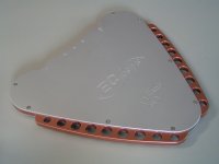
Two products are now based on this novel, discrete Mosaic DAC. The Mosaic 16 player (picture shows an early prototype) and the Mosaic 24 USB DAC that offers Hi-res support (same housing). Both have built-in 64 step relay volume control based on low noise nickel chrome precision resistors.
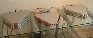
The MB2 evolved to the 160W rms Equilibrium monoblocks that are based on novel inter-active voice coil drive that offers unmatched performance over existing constant voltage or quasi constant current drive. Inter active drive gains total control over the most “difficult” to drive speakers, and saves a lot of energy. It is almost surrealistic to run the Equilibriums at top power for an hour, and then touching the housing with small heatsinks that remain only slightly warm to the touch. Without signal (idling) the Equilibrium monoblocks have highest housing temperature as 18 watts is dissipated (bias current).
Novel resolution enhancement circuits are used that offer required resolution of up to 18 bits. Inter-active voice coil drive recycles speaker back emf for high efficiency and cool operation of the monoblocks and the speaker voice coil. The lower voice coil temperature results in less compression as the resistance stays more constant.
I use 3.5mm Jack plugs and sockets exclusively in order to maintain target resolution, RCA plugs and sockets have too high mass and related Eddy current losses that erase detail. All mains transformers are laminated in order to reduce these Eddy current losses.
I attached a photograph of the new audio set, a Mosaic 16 player prototype driving two Equilibrium monoblock prototypes. The heatsinks of the Equilibrium monoblocks are not spray painted yet.
Bit perfect playback is not that easy to achieve with Windows.
Our Hi-res Mosaic 24 USB DAC has a built-in bit-perfect test that is very revealing. This test proves beyond a shadow of a doubt if a digital audio source offers and remains to offer bit perfect playback or not. All levels are tested, 2 x 65,536 levels with 16 bits stereo and 2 x 16,777,216 levels with 24 bits stereo.
One of -very- few ways to achieve bit-perfect playback in Windows XP is using iTunes for Windows or JRiver for Windows 7 & 8. Windows has very poor digital audio support and if I am correct even Windows 10 won’t support UAC2 (USB Audio Class 2).
Linux and MAX OSX are no problem as long as one verifies the settings and uses suitable players. These operating systems also support UAC2. So I -strongly- suggest to use one of these operating systems when highest audio performance is desired.
When bit-perfect playback is verified (data = data) there are still some other things that can cause audible degrading, interference on the digital signal (jitter, ripple) and ground loops.
Ground loops are formed when connecting mains powered equipment to a USB DAC. This can be a computer or a battery powered laptop with mains powered HDD or SSD drive connected to it for example.
USB isolators reduce the degrading effect of ground loops (stray capacitance prevents isolation for RF interference) but also add jitter to the passing USB signal, roughly around 100ps. So the cure can be worse than the ailment here.
USB jitter and ripple -always- ends up in the DAC output signal, there is no way preventing this, no buffer, no isolator, no reclocker. So one will -always- hear the degrading effect of digital audio source interference spectrum. It is well known that different computers, USB interlinks,OS and applications result in different perceived sound quality.
So if the sound quality of a computer based digital audio changes with different USB cables, tweaking of applications and drivers it simply shows the flaws and limitations of this digital audio playback concept.
The mechanism is simple:
Computer interference spectrum rides on the USB serial data signal in the form of timing fluctuations (jitter) and ripple on top of the data signal. Its spectrum is -filtered- by the USB interlink (cable impedance, stray capacitance, stray inductance, shielding and so on). So the USB interlink changes the USB interference -spectrum- that originates from the digital audio source.
It is also interesting to know that the interference mainly spreads through modulated carrier frequencies (modulated with interference) that are demodulated in connected circuits, revealing the contained interference. Since these carrier frequencies are very high, they can easily pass even low stray capacitance of a few pF in buffers, isolators and reclockers for example.
At the USB DAC the data enters the electronic circuits. The contained interference (jitter, ripple) of the USB data signal spreads across the circuits through crosstalk and demodulated carriers. This effect can be reduced but it is -impossible- to fully block it. So part of it -always- reaches the DAC output. Again, buffers, isolators and reclockers won’t be able to fully block this interference spectrum. The interference could only be blocked when DAC input circuit had zero bandwidth, but in this case it would be impossible to get any USB data into the DAC. I am not just talking about sample timing jitter but also amplitude distortion (interference super imposed on the output signal).
So interference generated by the computer circuits and pheripherals will become audible through the speakers. Therefore it is logical that reduction of interference on the computer can lead to different or even improved sound quality. This is probably how Rewrite data 1.05 functions, it reduces or changes the interference (spectrum) generated by the computer.
So computer-based audio will always be crippled by the presense of source interference spectrum that crosstalks to the DAC output. It is up to the user of such digital audio system if this degrading outweighs the comfort of streaming.
For this reason we developed the SD-player as it forms a -clean source- that minimises interference at the digital audio source. So the problem is tackled right at the source.
There are no ground loops as the SD-transport can be integrated in the DAC. This approaches the perfect digital audio source, bit-perfect playback is -guaranteed- by simply reading a WAV file from the card and converting it directly to I2S. Interference is minimised by using a single microcontroller with very low power consumption and very low related interference.
The SD-transport is slaved by the DAC clock for lowest possible jitter levels. The microcontroller with low interference also causes minimal masterclock degrading. Every circuit attached to a masterclock will degrade masterclock performance through stray capacitance. So the digital audio source also has -direct- impact on the masterclock slaving it! Clock buffers won't fix this issue due to stray capacitance and related crosstalk.
So in my humble opinion, the SD-transport concept offers significant advantages over computer-based streaming. It approximates the perfect digital audio source and when implemented correctly it offers highest obtainable performance.
But streaming is very popular and the higer bit depts and smple rates are tempting.
Perfectly healthy human auditory system can just resolve 18 bits under ideal conditions and for a short time period (risk of permanent hearing damage due to the very loud 0dB peak signal). Similar to the retina display that matches display resolution to the resolution of the human vision system, we could use 18 bits resolution as practical maximum resolution for the human auditory system. So bit resolution above 18 bits make no sense whatsoever as this exceeds the resolution of a perfectly healthy human auditory system.
Flaws in audio equipment reduce resolution to -well- below 16 bits, measurements can proove this. Suppose the peak voltage at the input of a power amp at practical volume setting would be 400mVpp. With 16 bits resolution, LSB change would be 0.4 / 65,536 = 6.1uV.
Take a function generator, set it at 1 KHz sine wave at 0.4 Vpp out and connect a resistive attenuator that attenuates approx. 65,000 times. For example 68K Ohms in series with 1 Ohm. Connect the power amp input across the 1 Ohm resistor.
Now go and sit in front of the speakers ad listen if you can hear the 1 Khz sine tone (the room must be dead quiet, without ambient sounds), if not, the power amp / speaker combination can’t resolve 16 bits. Reduce the attenuation factor to the point where the 1 KHz tone just becomes audible. One can now calculate the audio set true resolution.
Example, the tone becomes audible at an attenuation of say 10,000. This would correspond to 40uVpp. The practical resolution would now be 0.4 / 0.00004 = 10,000 levels or approx. 13.5 bits.
So in order to even hear the improvements of digital audio sources that actually offer higher resolution it is of greatest importance that this resolution is maintained by the connected power amp and speakers. It’s simply a matter of the weakest link.
Late 2014 I started development of a novel D/A converter after I had given up on D/A converter chips that are plagued by many uncorrectable design flaws. This finally lead to a discrete 16 / 24 bit D/A converter based on novel digital logic circuits and a novel D/A conversion concept (no delta sigma, no multi-level delta sigma, no R2R ladder DAC, no segmented R2R ladder DAC). This results in transparent sound, finally …. after more than 7 years of extensive research.
This novel D/A converter received the name Mosaic DAC as it takes bits and pieces (digital audio) and converts this into a musical piece of art. The module with many tiny chips on it also resembles a mosaic. The Mosaic DAC eliminates determinitsic jitter, offers unmatched SN ratio, offers extremely accurate timing (ultra high speed logic) and high bit accuracy. Every single chip is separately decoupled, this is impossible with a single DSAC chip. very low noise parts are used that simply cannot be integrated on a DAC chip.
It’s buffered voltage output completely eliminates all issues with I/V conversion and output compliance and offers maximum obtainable resolution.
The Mosaic DAC module requires one digital power supply (1V8) and one analogue power supply (3V3). Power consumption is very, low and the Mosaic DAC runs stone cold and requires no warm-up period like the TDA154x for example.
The Mosaic DAC module supports sample rates up to 1.5 Mega samples per second at 12.5% data density and has a separate TLE input for extremely accurate output latching. The TLE signal is generated by a novel MTM (Master Timing Module) by means of masterclock division (divide_by_256) based on an ultra high speed synchronous counter with coicidence phase locking (fuzzy logic).
The Mosaic DAC module measures 84 x 76 millimeters. PCB is routed single sided with wire bridges and is located over a solid ground plane (basically a 3 layer design). It takes a few days to assemble, test and calbrate a Mosaic DAC. The Moisaic DAC forms a matched pair with Microchip controller (SD-transport) or XMOS (USB DAC), the controller holds a unique “digital lense” that compensates for the unique component tolerances in the attached Mosaic DAC, ensuring very high accuracy without trimming. This means that the MOSAC DAC can’t be used with existing digital audio sources as these don’t offer the highly complex, real-time digital lens correction.
I developed a Mosaic 16 stereo DAC that already offers higher resolution than most audio sets can handle. The Mosaic 24 stereo flaggship DAC can be used to ensure full 18 bits resolution that perfectly matches the human auditory system.
Two products are now based on this novel, discrete Mosaic DAC. The Mosaic 16 player (picture shows an early prototype) and the Mosaic 24 USB DAC that offers Hi-res support (same housing). Both have built-in 64 step relay volume control based on low noise nickel chrome precision resistors.
The MB2 evolved to the 160W rms Equilibrium monoblocks that are based on novel inter-active voice coil drive that offers unmatched performance over existing constant voltage or quasi constant current drive. Inter active drive gains total control over the most “difficult” to drive speakers, and saves a lot of energy. It is almost surrealistic to run the Equilibriums at top power for an hour, and then touching the housing with small heatsinks that remain only slightly warm to the touch. Without signal (idling) the Equilibrium monoblocks have highest housing temperature as 18 watts is dissipated (bias current).
Novel resolution enhancement circuits are used that offer required resolution of up to 18 bits. Inter-active voice coil drive recycles speaker back emf for high efficiency and cool operation of the monoblocks and the speaker voice coil. The lower voice coil temperature results in less compression as the resistance stays more constant.
I use 3.5mm Jack plugs and sockets exclusively in order to maintain target resolution, RCA plugs and sockets have too high mass and related Eddy current losses that erase detail. All mains transformers are laminated in order to reduce these Eddy current losses.
I attached a photograph of the new audio set, a Mosaic 16 player prototype driving two Equilibrium monoblock prototypes. The heatsinks of the Equilibrium monoblocks are not spray painted yet.
Attachments
¡Great news!
My dear -EC-. it is always a pleasure to hear good news from you.
You know I have been your fan n°1 since you started and I want prototype n°1, with an autograph 😎
You are correct about the problems in digital transmision/reproduction, as always. The point is that the trick the "rewrite data" software does is useful and even noticeable when you "treat" the music inside the SD cards, as I confirmed in my humble Dual-Mono TDA1543 DAC.
BTW, I was about to write that in cannot imagine how good a Dual-Mono TDA1541A would sound, but now that you came with the Mosaic it is futile to comment, I guess...
About bit depth, I agree. The attractive of the archaic TDA1543 is the corporeity of the sound, the weight of the midbass and the organic nature of the instruments' textures, even if one loses detail...and now that I have enormous dynamics, thanks to the Dual-Mono configuration (the attacks on the piano notes make me fear!) I couldn't be happier with my improbable success, given my lack of knowledge. I guess that the absence of slew rate degradation given by the passive honeycomb resistor I/V passing 4,6mA is the culprit of the explosive nature of the dynamic constrasts...this DAC is violent!
So DeltaSigma are good for casual listening, but I always return to my raw and wild player.
I am still making test with different configurations. Next: newer Vregs; only pin 8 output; DC coupling. So there is still room for improvement.
I finally had the time and energy to try your shunt regulators (not used yet, maybe today) and I tested the behaviour compared to the other Vregs I have: TeddyRegs for the digital sections and Super teddyRegs for the DAC chips. I noticed that all had noise on the mV range and when I lowered the scale I discovered that all show a (+/-)6Mhz (could be 12Mhz) sine that polutes all power sections. I believe these are ground currents, like an "internal ground loop", molesting all circuits. So I plan to make a star ground and add ferrites to all ground wires. I also have to add ferrites near logic chips' power pins, as Guido Tent recommends. I guess low value resistors for the logic chips interconnections won't hurt either...
For a long time I have been wanting to buy your SD player with TDA1541A, but I refrained due to:
1) It won't be DIY anymore. 🙁
2) I hate to pay taxes/duties. 😡 (this would be an excellent excuse for a trip to Holland 😀)
3) I don't need the integrated volume control section since I'm stuck to my Stevens&Billington's Transformer Based Volume control. I think this is due to the minimal loss of musical energy that the high quality Tx affords. It would be a good move to offer the Volume Control section as an option. 😉
4) I was waiting for the last distillation of your mInd's powers...and now I think we arrived to the goal...John, you have to patent your idea, man!
Thanks for the privilege of having been witness of your ascending path in audio for the last years. 😎
(I keep record of our communiction and I study it from time to time to try to understand what you explain 😕)
Sincerely yours,
M.
Last edited:
Hi John! So exiting to hear in more detail your progress.
I will get your new equilibrium amps as soon as they are available! Do the Equilibrium still use circlotron output? is it still lateral mosfet output? could you share more information about your amps and how they compare to your MB2?
thanks!
I will get your new equilibrium amps as soon as they are available! Do the Equilibrium still use circlotron output? is it still lateral mosfet output? could you share more information about your amps and how they compare to your MB2?
thanks!
- Home
- Source & Line
- Digital Line Level
- Building the ultimate NOS DAC using TDA1541A