ok - audiokit-italy is a 100% legit company with great service. makes me regret i did NOT order MORE stuff from them. i actually received today my order from them (the coils and resistors) about less than a week - i orderedes 25/5 and today i have the gear...
good to know for next time i need something 😀
feels nice to see the components... hopefully the germans (strassacker) will not take too much longer before they also send the gear. with luck, in about 2 weeks time im set to start soldering etc.
im stoked 😀
good to know for next time i need something 😀
feels nice to see the components... hopefully the germans (strassacker) will not take too much longer before they also send the gear. with luck, in about 2 weeks time im set to start soldering etc.
im stoked 😀
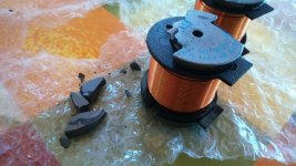
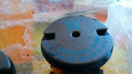
i got today the order from audiokit.it - but unfortunatelly 2 of ferrite coils are broken into pieces. had no option but send them some pics, and fill the RMA slip. i hope they undertand they need to package these kind of items better...
now ill see how long time the RMA will take, and the delivery process.
at least the rest of the coils and resistors are ok.
now ill see how long time the RMA will take, and the delivery process.
at least the rest of the coils and resistors are ok.
but unfortunatelly 2 of ferrite coils are broken into pieces.
Bummer... 🙁
ive been talking to audiokit.it and they have offered to replace the coils with better ones since the coils above are out of stock and production. they even sent an message this morning saying the new better coils are already sent. this far their customer service has been top class. ill give a definitive valuation of their service once i get the replacements 😀
also i have ordered pretty much everything i need, even the solder and some extras that will be part of the final design.
only thing left is to get a new collet nut for my router 😀
soon enough i can get going with the build 😀
also i have ordered pretty much everything i need, even the solder and some extras that will be part of the final design.
only thing left is to get a new collet nut for my router 😀
soon enough i can get going with the build 😀
yesterday i ordered 2 pieces of clear acrylic, 5mm thick to use as a cover for the crossovers.
ive been today in the workshop trying to figure out a nice way to use the pieces of acrylic i bought online (which i got this morning, about 16 hours after the order! the company is close - only 5km hehe)..
anyway i decided to make a frame where the acrylic sheet fits inside, and its hold in place by round polished brass nuts which fit onto threaded inserts in each corner. like this i dont need to to drill any holes in the edges of the acrylic.
also since the entrance to the crossover will be through the acrylic, i thought id try an idea i had. i will glue a piece of hardwood onto the acrylic sheet and fit the binding posts thru the wood and acrylic. like this there will be less strain on the acrylic and it should keep for longer without cracking.
im also considering to put a piece of wood on the inside of the acrylic as well. i will have to dig through the scraps pile to see what i have...
an LCR-meter - is definitely a use-full item. the problem is i spent my budget for the speaker build project. an other 30 euro now is really not what i really want to spend 😀 hehe but the problem is i need to adjust the inductivity of 4 small copper coils. from 0.39mH to 0.35mH and 0.22mH to 0.20mH.
i could simply un-wind the coils entirely, and measue the length and cut of a bit less than 10% - but im a bit worried it wont look as neat once im done re-winding the copper-coils..
i could simply un-wind the coils entirely, and measue the length and cut of a bit less than 10% - but im a bit worried it wont look as neat once im done re-winding the copper-coils..
i could simply un-wind the coils entirely, and measue the length and cut of a bit less than 10% - but im a bit worried it wont look as neat once im done re-winding the copper-coils..
I wouldn't do that. Just unwinding and winding without changing the length can change the inductance.
i could simply un-wind the coils entirely, and measue the length and cut
of a bit less than 10% - but im a bit worried it wont look as neat once im
done re-winding the copper-coils..
That would be unnecessary. Simply unwind 90 cm from 0,39mH and 60 cm
from 0,22mH. I have checked with a coil calculator asuming 1 mm wire thickness
and 20 mm of inner diameter, air core.
thanks a lot Lojzek! 😀
i went and i checked the coils 🙂 its 0.71mm diameter wire, and indeed the inner diameter is 1.4cm (14mm). coil length is 3cm
i went and i checked the coils 🙂 its 0.71mm diameter wire, and indeed the inner diameter is 1.4cm (14mm). coil length is 3cm
Last edited:
im trying to use this Pronine Electronics Design - Multilayer Air Core Inductor Calculator but i really dont know if its a reliable calculator or if im using it right 😀
what makes me think i do something wrong, is the fact the calculator gives me a different ohm rating to the one written on the coil. i dont know if that is relevant or not. ?!
0.71mm diameter wire is 21 Wire gauge
the calculater says the wire length;
0.39mH is 12.29m, 0.35mh is 11.61m (remove 70cm?)
0.22mH is 9.2m, 0.20mH is 8.76m (remove 44cm?)
im downloading a program called coil32 (Coil32 - the coil inductance calculator) to calculate again to see if i get similar values. (if i will understand that program that is hehe)
the program coil32 gives slightly different length to the wire, but the difference to cut of remains the same, cut off 69cm for the 0.39mH to 0.35mH coil and 45cm from the 0.22 mH to get 0.20 mH.
am i on the right track?
am i on the right track?
floobydust
I wouldn't sweat it till yer almost done with everything else
this is 10% on a piece of paper, not much in the land of speaker modeling.
you know the tolerance of the caps might be in the other direction, so it could be a good thing. Or your box dimensions and driver mounting can account for some errors. who really knows the direction of all the errors. maybe later on youll come across a borrowed L/C meter or an laptop sweep can let you decide more accurately.
Hi,
+1 with infinia
First do nothing because the values are 10% around the correct value.
I measure accurately coils and caps with REW and an impedance mesurement.
You need a PC,REW and an impedance jig as shown in this picture :
Impedance Measurement
It costs just few € two RCA plug, a 100 ohms 1% resistor and a RCA / jack cable.
am i on the right track?
Yes, you are. LU44 coils are 1 mm wires by default, so their dcr is lower,
LU32 are 0,71 mm. Calculator is not wrong in calculating higher dcr with
thinner wire. Markings on the inductors might be.
As has already been said, the difference may not be of any real importance.
thanks guys 🙂
the 0.20 mH coils is for the notch filter for the mids - i worry a little bit about if the notch filter will be affected negatively from not adjusting this to the exact value. i have limited knowledge - i admit this 😀 but i read now the L and the C in a notch filter determines the center frequency of the notch filter, so my fear is IF the "notch" will be offset from the peak it is supposed to tame... 😀 and if this might seriously mess up the sound..
i do not know how to calculate the difference the 10% would make here, but out of the two coils, this is the one that worries me. somehow i got the impression the 0.39mH coil in the highpass is less noticeable. i might be wrong 😀
Hi,
You can simulate with free software (SW, XSim) or for the RLC simply use the online calculator below :
Iris Strassacker, solutions HiFi plus de 500 kits d'enceintes à votre choix
Outils -> Calculateurs -> RLC
Rmin at 4900 or 5192 Hz. with 0.22 or 0.20 mH and 4.7 mF.serie.
You can simulate with free software (SW, XSim) or for the RLC simply use the online calculator below :
Iris Strassacker, solutions HiFi plus de 500 kits d'enceintes à votre choix
Outils -> Calculateurs -> RLC
Rmin at 4900 or 5192 Hz. with 0.22 or 0.20 mH and 4.7 mF.serie.
Last edited:
Fnotch=1/(2*PI*SQRT(L*C))
best is to measure drivers peak 1st and resultant notch after.
next best is calculate notch from measured values of both L&C.
you can see it depends on both tolerances direction +/-
deepness of notch depends on Q of the network R= Rlc +R
L= +10%
C= -5%
result is notch freq is off by only 5% this can be minimized further by adjusting R to cover a broader range
assumption > your driver peak matches the design target
even if you pay the big bux to get 1% parts it can still be off, due to drivers response changes from part to part and operating drive level.
Last edited:
- Status
- Not open for further replies.
- Home
- Loudspeakers
- Multi-Way
- building the TARKUS