Fair enough , I like the attitude and reasoning. I am too only interested in " best in the world " and don't want to waste my time on anything less .Hmm. Did you understand first post as my claim that this is THE ultimate amplifier (best in the world)? If so, read again please.
I wouldn’t like that any subjective vs. objective discussion enter this thread. What I listened to in my home (or not) wouldn’t change what I’m able to design even if knowing that something could be better. There are limits and compromises.
Technically (by numbers) this amplifier is mighty fine. My subjective description is actually toned down as my opinion and impressions doesn’t count much (possible bias).
After other members build this amplifier, we will know more for sure.
The transformer combination of >150VA and 14V secondaries per channel has thrown me a curve ball. Decent VA and low output voltage is a combination I don't have in my vast donut collection.
Looks like a new pair of trafo's will be on the way.....
Looks like a new pair of trafo's will be on the way.....
Yes, I have been looking at that as well Vunce, are you still doing a reg supply at +/- 17.5VDC?
Yes, I'm going to give Tombo's "R21" a try with this build. Also will be using active rectification, this should offset most of the voltage drop from "R21".
Antek Transformers have gone up in price significantly in the past year, so the difference in cost compared to a custom wound Toroidy is not as great as it once was.... deep thought here
Antek Transformers have gone up in price significantly in the past year, so the difference in cost compared to a custom wound Toroidy is not as great as it once was.... deep thought here
Good one Vunce, I will also use Prasi's active rect boards, then to CRC then to +/- reg to give me +/-18VDC to amp pcb's So I am thinking 18VAC secondaries as I need about 4 volts across the regs. Still deciding whether to go dual mono for the PSU.
Just checked and I do have 2 toroids that will suffice.
I have 2 of each of the active rectifier, CRC and +/-reg supply boards done- will start on the amp pcb's early new year - along with the F6 revisited diamond buffer / dual SLB's.
Just checked and I do have 2 toroids that will suffice.
I have 2 of each of the active rectifier, CRC and +/-reg supply boards done- will start on the amp pcb's early new year - along with the F6 revisited diamond buffer / dual SLB's.

Yes, it is. It is a little cramped for build with dual mono supplies, but I wanted a compact build. At 1 A bias, heatsinks temperature rise over ambient is 15° C.
Well done Vunce, how did you go soldering those tiny smd LT4320's? I am glad I have a stash of the DIP version of these.
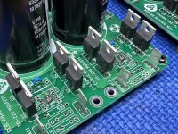
Also, what Mosfets are they that you are using? I don't recognize the part number in your photo.
Also, what Mosfets are they that you are using? I don't recognize the part number in your photo.
Thanks G.
Paste, hotplate from bottom, hot air from top. This method ensures the MSOP12 belly pad is soldered.
Mosfets - IPP029N06N
There was a time when the LT4320 in MSOP12 package was about half the price of the DIP8 version, I stocked up on them. But now the prices are basically equal☹️
Paste, hotplate from bottom, hot air from top. This method ensures the MSOP12 belly pad is soldered.
Mosfets - IPP029N06N
There was a time when the LT4320 in MSOP12 package was about half the price of the DIP8 version, I stocked up on them. But now the prices are basically equal☹️
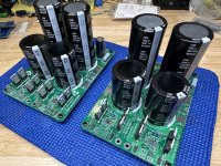
Hey Vunce nice build whats this "R21" modules?Made some power supply progress this weekend, 22mF first cap, 47mF second cap.
Next step: build “R21” modules.
I see superb soldering at every PCB position. More than well done. 🙂Made some power supply progress this weekend, 22mF first cap, 47mF second cap.
Next step: build “R21” modules.
Big output capacitors are not required with R21 voltage regulators but they don’t hurt either. In fact, they help a little with PSRR at very high frequencies. In my build output capacitors are 10 mF. They are big because of long life (13.000 h) & 63V properties.
I believe you have a Quasimodo jig. Don’t bother with snubbers in case of active rectification. I’ve measured a lot and ringing is practically nonexistent (10 -100 times lower than with diode bridges). Nothing to measure as induced noise at PS output or amplifier circuit.
Agree , Vunce seems to be very proficient with the soldering iron - members should take note of that.
Thanks for the tip with regards the snubbers when using active rectification. Vunce must have known that as he has not loaded those components.
Thanks for the tip with regards the snubbers when using active rectification. Vunce must have known that as he has not loaded those components.
I can swap the tall caps for another pair of 22mF instead, they are not visually appealing 😂. I plan to add a 120uF motor run PP cap at each ps output rail (4 total).
Cleaning the flux residue will make anyones soldering look better😁.
Tombo,
Reading/researching about active rectification supports your real measured findings with regards to not requiring snubbers, so I don’t populate them.
Cleaning the flux residue will make anyones soldering look better😁.
Tombo,
Reading/researching about active rectification supports your real measured findings with regards to not requiring snubbers, so I don’t populate them.
When amplifier lid is closed, it doesn’t matter but will it ever be closed? Mine still isn’t. 😀I can swap the tall caps for another pair of 22mF instead, they are not visually appealing 😂.
You’ve approached PS build as it will be a standard CRC. With voltage regulators rules are different.
22 mF at output is fine. Another option is to swap capacitor positions and put 47 mF as a first reservoir cap. R21 voltage regulators actually don’t require any capacitance at output for stability and their output impedance is 40 uΩ at 20 kHz. In example, here is R21 output under transient load with no capacitance at output (well, there is likely 100 pF parasitic capacitance). Yellow is regulator output and blue trace is voltage measured at active load 0.085 Ω, so transient load is 5 A peak half sine repeated at 20 kHz rate.
Don’t bother with motor-run capacitors. Amplifier has all the decoupling capacity required and motor-run capacitors will have no effect. Amplifier will provide perfect 100 kHz, +/-15 V square wave response with no ringing or overshot even with simple CRC power supply.
Some points about PS are at post #35.
In general, if using two prasi’s CRC boards with active rectifiers, you need two 2 x 12 V to 2 x 13 V, 120 – 150 VA transformers or one 300 VA with 4 secondaries.
With one PS board for both channels, you need 2 x 14 V, 250 – 300 VA transformer. Small overvoltage can be mitigated as explained in post #35.
- Home
- Amplifiers
- Solid State
- Building an ultimate low power class A amplifier – my way