I wouldn't pretend that I have the energy to scrutinize your layout for connections (40C here). Just make sure it follows the schematics accurately.
But others may spot something or not.
Unfortunately super bright LEDS have a reputation for being noisier than normal ones which I can not confirm how much right now.
But surely I have never seen them in instrumentation as voltage references. Better use 3mm generic reds or greens in the 3+5 proven configuration.
Oh, I see that why no one use bright LED's...
I will change to original 3 + 5 that has proven configuration & check again if any error
maybe I'll give it a try in few days 😎
I need buy some LEDs 🙂
Good luck then. What kind of amplifier you project it to drive? Does it have at least 26dB of gain so a buffer will bring enough sound pressure level?
I wouldn't pretend that I have the energy to scrutinize your layout for connections (40C here). Just make sure it follows the schematics accurately.
But others may spot something or not.
Unfortunately super bright LEDS have a reputation for being noisier than normal ones which I can not confirm how much right now.
But surely I have never seen them in instrumentation as voltage references. Better use 3mm generic reds or greens in the 3+5 proven configuration.
You are not the " Central Scrutinizer " ( Frank Zappa ) . 🙂🙂🙂
Dissapointed
I heard the buffer yeasterday and I am sorry to say I was very dissapointed. NICE but booring.
I heard the buffer yeasterday and I am sorry to say I was very dissapointed. NICE but booring.
Try a triode tube buffer.
Hehe 🙂 the only thing we need the buffer for is between an Dac with tube output and only 0,47 uf into our Balanced bride off Zen with 25 kohm input impedance. Maybe it will perform allright in that setup.
Subjectively whatever you prefer. Just make sure that the total gain and its structure is sufficient in any given system from source to speakers..
Sunny Sunday... &Hi everyone,
I've read all post here from page 1 to last one... need some days 😀
My handycraft PCB almost done ... 😎
time to do some holes 😀
Hi Erlend, why it is NICE but make you disappointed?I heard the buffer yeasterday and I am sorry to say I was very dissapointed. NICE but booring.
Maybe any wrong setup, could you tell us the story
I'm going to made it, wish me like it 🙂
Attachments

Last edited:
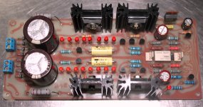
PCB is done
Hi, ...
this is my finished hand made PCB ... but it will be slowly build 😎
Hi, ...
this is my finished hand made PCB ... but it will be slowly build 😎
An externally hosted image should be here but it was not working when we last tested it.
Hi Udailey, thx...
I use permanent marker & hand drawing
it is my old way but you can try it, it's fun & work very well on me.
well I hope I can explain what I do correctly:
First I print the layout in a paper, than make a sandwich (paper on top the board)
with a little hammer hitting the steel needle I made a mark on the copper side, so dot's (a little hole made by the needle) everywhere on the copper plane. The little hole help a lot to guide you to drawing on the blank copper plane (also when drilling the pads make more accurate). Then I start to draw pads, all pads, all traces,... that quite exiting 🙂
Double or triple the layer with permanent marker for best result (I even add refill ink on new marker, they dried fast)
Error drawing, don't worry fix with it :
"the magic pencil"
http://imageshack.us/a/img850/549/tusukjarum.jpg
That why it is called PCB arts-work 😀
ps: I'm sorry for this off topic
Regards
I use permanent marker & hand drawing
it is my old way but you can try it, it's fun & work very well on me.
well I hope I can explain what I do correctly:
First I print the layout in a paper, than make a sandwich (paper on top the board)
with a little hammer hitting the steel needle I made a mark on the copper side, so dot's (a little hole made by the needle) everywhere on the copper plane. The little hole help a lot to guide you to drawing on the blank copper plane (also when drilling the pads make more accurate). Then I start to draw pads, all pads, all traces,... that quite exiting 🙂
Double or triple the layer with permanent marker for best result (I even add refill ink on new marker, they dried fast)
Error drawing, don't worry fix with it :
An externally hosted image should be here but it was not working when we last tested it.
"the magic pencil"
http://imageshack.us/a/img850/549/tusukjarum.jpg
That why it is called PCB arts-work 😀
ps: I'm sorry for this off topic
Regards
Last edited:
Hi, ...
this is my finished hand made PCB ... but it will be slowly build 😎
An externally hosted image should be here but it was not working when we last tested it.
Vintage cool diy with curved vias. Great.

I guess it's ready to test
sorry for very late reply, ...the amp is 30dB & another one 40dB...
Today I almost done it, I want to test the voltage first before put the missing 2SK170 pairs
because I can't get 1.8 volt LED's so I use 1.88 volt instead.
I hope nothing bad happening 😉
Regards
Hi Sir Salas,Good luck then. What kind of amplifier you project it to drive? Does it have at least 26dB of gain so a buffer will bring enough sound pressure level?
sorry for very late reply, ...the amp is 30dB & another one 40dB...
Today I almost done it, I want to test the voltage first before put the missing 2SK170 pairs
because I can't get 1.8 volt LED's so I use 1.88 volt instead.
I hope nothing bad happening 😉
Regards
Attachments
Last edited:
Looks it turned out good. Don't worry about that small Vf extra in the LEDs. Its how they produce them now.
DCB1 is Ready to Rock
Hi all...
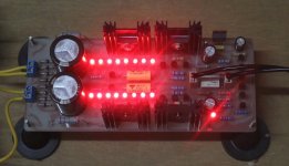
I measured the voltage today & they are okay I guess 🙂
so I put the 2SK170 pairs & they are a bit warm 😎
Hey, they are working
maybe tomorrow I will surprise with the sound
Warm Regards 🙂
Hi all...
I measured the voltage today & they are okay I guess 🙂
so I put the 2SK170 pairs & they are a bit warm 😎
Hey, they are working
maybe tomorrow I will surprise with the sound
Warm Regards 🙂
Attachments
Last edited:
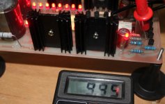
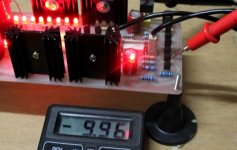
Fine until now. Verify that the relay clicks to engage the audio outputs. You should measure some DC offset at the audio outputs. If it is lower than 5mV it is acceptable.
All Ok, thanks to all
The relay clicks after few seconds, I just use BC550C for relay(no BC517 available here locally).
DC offset is below 5mV, the DC offset was about -1mV to -2mV.
Thank's for Salas for this wonderful circuit...
& Nelson Pass for the B1.
If anyone want to try it too I will give the layout 🙂
or should I post it here?
Regards
It all fine... 🙂Fine until now. Verify that the relay clicks to engage the audio outputs. You should measure some DC offset at the audio outputs. If it is lower than 5mV it is acceptable.
The relay clicks after few seconds, I just use BC550C for relay(no BC517 available here locally).
DC offset is below 5mV, the DC offset was about -1mV to -2mV.
Thank's for Salas for this wonderful circuit...
& Nelson Pass for the B1.
If anyone want to try it too I will give the layout 🙂
or should I post it here?
Regards
It all fine... 🙂
The relay clicks after few seconds, I just use BC550C for relay(no BC517 available here locally).
DC offset is below 5mV, the DC offset was about -1mV to -2mV.
Thank's for Salas for this wonderful circuit...
& Nelson Pass for the B1.
If anyone want to try it too I will give the layout 🙂
or should I post it here?
Regards
Please post your layout 🙂
I like it 🙂
When I use the amp with a bigger gain, the difference is not so much
(maybe amp was not built properly by me 😀)
Then I use the PeeCeeBee ...
Now I could feel my work is more alive, what a surprise ...
If I said the amp is only 50W then they (some people here, nearby) will say I was lying because the sound is so loud.
Better bass, mid, & high,
when I use tone control in the amp,
I turn to max position(not the volume) & no "over control" like before.
The DCB1 make it straight like what it is should be
I like it so much, maybe I should make it again some day 😎
Please note that I'm use cheap source that built in volume & remote control so I don't use 20k pot (but I already order it).
So next time I must use better setup 🙂 & get ready for another better story
Ok, I will post it tommorow cos the PC I use is being repaired
there will be bottom & top component placement, jpg & pdf 🙂
Yes, I did it ...Congratulations. Did you put it in your audio system too?
When I use the amp with a bigger gain, the difference is not so much
(maybe amp was not built properly by me 😀)
Then I use the PeeCeeBee ...
Now I could feel my work is more alive, what a surprise ...
If I said the amp is only 50W then they (some people here, nearby) will say I was lying because the sound is so loud.
Better bass, mid, & high,
when I use tone control in the amp,
I turn to max position(not the volume) & no "over control" like before.
The DCB1 make it straight like what it is should be
I like it so much, maybe I should make it again some day 😎
Please note that I'm use cheap source that built in volume & remote control so I don't use 20k pot (but I already order it).
So next time I must use better setup 🙂 & get ready for another better story
Hi, RCruz only if you want to build it fast 😀Please post your layout 🙂
Ok, I will post it tommorow cos the PC I use is being repaired
there will be bottom & top component placement, jpg & pdf 🙂
- Home
- Amplifiers
- Pass Labs
- Building a symmetrical PSU B1 buffer