Thanks for your input.
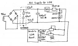
Hi Uriah. That is very interesting about capacitive coupling on the LDRs. My supply is perhaps already similar to what you suggested (see circuit below). Do you think the Oscons are ok as final filtering elements? Any other suggestions for mods are welcome.
I think the problem I had might have been exacerbated because I use an LC filter after the rectifier bridge. This caused a weird looking waveform on the output of the bridge which seemed to also upset the transformer and produce some additional ringing on this and other windings.
The snubber I fitted is shown on the diagram. The waveform there is still strange, however the sharp resonances noticed on all windings are gone.
As an interesting bonus this snubber even eliminated the minor ringing on other windings which was generated independently of this circuit.
Jeremy
Attachments
Last edited:
Problem located and fixed
The hum problem is located and fixed.
It was a grounding failure on the psu pcb in my F5!
Thanks and best regards to all,
Oliver

Hi Albert,
i tried that. A bit better like the Nordost cables i had tried, but the hum is still there...😕
The hum problem is located and fixed.
It was a grounding failure on the psu pcb in my F5!
Thanks and best regards to all,
Oliver
You may be getting an earth loop between channels out one interconnect lead and back in the other.
.
Hi dvb-projekt it seems reading your link I was on the money, though of course I didn't give any pointers as to where to look in the amp for the problem. Glad you got it sorted 🙂
Tony.
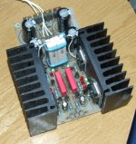
Well I went ahead and cut the DCB1 PCB in half and now have a SALAS Shunt Reg that I can use with my B1.
I've reduced the series resistors to 10R and added heatsinks.
Question is - Why are the resistors so massively specified ?
By my measurements with the original 22R resistors VR = 1.4V.
Now that I have 10R, I=E/R so I = 1.4/10 (which equals 140mA)
The resistors are only going to be dissipating I^2R = 0.14x0.14x10 = 0.2W
I/ve used 10W because that is what I happened to have.
Attachments
Under test VR has crept up slightly on one rail to 1.77V but stays at about 1.58V on the other.
That means that I am running 177mA +/- 10% on one and 158mA +/- 10% on the other.
I'm letting it cook to see how warm it gets.
(The tolerance by the way is the tolerance of the power resistors).
That means that I am running 177mA +/- 10% on one and 158mA +/- 10% on the other.
I'm letting it cook to see how warm it gets.
(The tolerance by the way is the tolerance of the power resistors).
Get some 3r3 resistors. Listen to the 10 first and the switch to 3r3. If you want, you can use dip sockets or soldering post to make swotch easier. I guarentee you will hear a difference. Dont worry about difference in current, it matters not.
I'll order some in as I haven't got anything that low.
I like to keep things tidy so I wont be bunching up a boxful of 10Rs to try them.
Heatsinks are running at a cool 27 Degrees with ambient at 19 Degrees.
I like to keep things tidy so I wont be bunching up a boxful of 10Rs to try them.
Heatsinks are running at a cool 27 Degrees with ambient at 19 Degrees.
Just doing a bit of mental maths to make sure everything will be OK.
As heat transfer and everything else is linear.
Currently my heatsinks are 8 Degrees above ambient - nice and cool.
If I triple the current will this triple the heat - ie heatsinks 24 degrees above ambient ?
If everything stays linear the sinks will then run at about 43 Degrees.
????
Unfortunately I have no idea what the dissipation figure for these old reclaimed sinks is.
Should be OK. THe IRF's are tough. You can judge then if you have enough. What is the reating on your trafo secondary?
Should be OK. THe IRF's are tough. You can judge then if you have enough. What is the reating on your trafo secondary?
15-0-15 60VA
The best of both Worlds
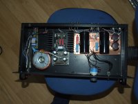
After a great deal of playing, I've now settled in for this weekend with my B1 running with the Salas Shunt reg. set at 180mA.
I do think that 600mA might get a bit warm in there but I might try 500mA later.
The B1 is a far more forgiving board when it comes to laying it out and is completely silent. A correctly laid out DCB1 is silent too, don't get me wrong.
I can use my wonderful Obbligato 10uF PIOs in this layout which suits me as I have a DC coupled amp.
The B1 doesn't need the dual reg, but, hey I'd built it anyway so I'm just using is as a 19V DC supply.
No humming, no buzzing and no distortion. Just pure listening pleasure. No relays, No turn-On thump, just everything as I would like it.
Attachments
Last edited:
Thanks for your input.
Hi Uriah. That is very interesting about capacitive coupling on the LDRs. My supply is perhaps already similar to what you suggested (see circuit below). Do you think the Oscons are ok as final filtering elements? Any other suggestions for mods are welcome.
I think the problem I had might have been exacerbated because I use an LC filter after the rectifier bridge. This caused a weird looking waveform on the output of the bridge which seemed to also upset the transformer and produce some additional ringing on this and other windings.
The snubber I fitted is shown on the diagram. The waveform there is still strange, however the sharp resonances noticed on all windings are gone.
As an interesting bonus this snubber even eliminated the minor ringing on other windings which was generated independently of this circuit.
Jeremy
Jeremy,
Your supply should do the trick. Oscons are nice. I find them expensive. A Nichicon or Panasonic will give you the same effect. Dont forget to throw a film on the electrolytic's leads.
Uriah
just everything as I would like it.
Since you had output capacitor in service anyway, a good config decision. Enjoy.
Jeremy,
Your supply should do the trick. Oscons are nice. I find them expensive. A Nichicon or Panasonic will give you the same effect. Dont forget to throw a film on the electrolytic's leads.
Uriah
Great. I found the Oscons in my parts bin and thought "what the heck". Best I delve back in their for a film cap too.
Thanks for the advice.
Jeremy
I have a partial kit for the DCB1 mesmorize available if anyone is interested.
http://www.diyaudio.com/forums/pass-labs/207646-help-where-i-can-buy-dcb1-kit.html#post2925027
http://www.diyaudio.com/forums/pass-labs/207646-help-where-i-can-buy-dcb1-kit.html#post2925027
Last edited:
I'll reflect that in the advert, I only used two input channels so I would only use three.
I missed that as I used my B1 board that didn't use any relays.
I missed that as I used my B1 board that didn't use any relays.
Last edited:
I've just received my 3R3 resistors.
Unfortunately they were sold under a banner that did not read correctly
FOR SALE 3R 3Ohm Resistors. I assumed that was 3R3 but they are 3R0 or 3Ohm.
Never mind. Do you think 3R0 may be a little too low for my heatsinking ?
Unfortunately they were sold under a banner that did not read correctly
FOR SALE 3R 3Ohm Resistors. I assumed that was 3R3 but they are 3R0 or 3Ohm.
Never mind. Do you think 3R0 may be a little too low for my heatsinking ?
You can always just try them. Keep an eye on the temp as it warms up. You wont kill anything if you plan ahead to turn off at a given temp and have a way to measure temp.
- Home
- Amplifiers
- Pass Labs
- Building a symmetrical PSU B1 buffer