You had enough field interaction beyond what you are to find next after all. Good work till now, happy vacation.
You had enough field interaction beyond what you are to find next after all. Good work till now, happy vacation.
Thanks Salas
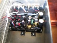
Malka insert a 1 ohm resistor direct after each rectifier. The peak currents introduce current spikes which in turn creates EMI.
I always use 300uH direct after all rectifier briges before any electrolytics.
toroid inductors is good since the leaking field is low.
Martin P
I always use 300uH direct after all rectifier briges before any electrolytics.
toroid inductors is good since the leaking field is low.
Martin P
Thank you, Salas. When I'm late to the party, I want to check the invitation to make sure of the correct attire.😉For the circuit look in the very first pages. You are actually holding a live BOM by having an assembled unit 🙂 but here is the link. http://www.diyaudio.com/forums/grou...led-b1-buffer-shunt-psus-140.html#post1959250
Another Hypnotize is born. Thanks for the help and props for the design and board work.
What type of attenuator is that.
Another Hypnotize is born. Thanks for the help and props for the design and board work.
Nice one, did you ear it yet?
What type of attenuator is that.
It's a Goldpoint.
Westend built that beauty for me! Can't wait to get it hooked up to my F5 monos.
I've forgotten how you edit over here at DIY but don't follow my depicted mistake, above. I don't know what I was thinking but I managed to get the input and output wiring reversed. It is now oriented correctly.😀
Strange thing, I was driving along and was thinking about this project when it dawned on me. When I got home I brought this thread up and looked at the first attached picture from my previous post. Yup, I are backwards.😱
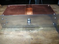
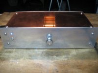
Attached is a picture of the finished case. Mr. Fud is going to like this, methinks.🙂
Strange thing, I was driving along and was thinking about this project when it dawned on me. When I got home I brought this thread up and looked at the first attached picture from my previous post. Yup, I are backwards.😱
Attached is a picture of the finished case. Mr. Fud is going to like this, methinks.🙂
Attachments
It's a Goldpoint.
Westend built that beauty for me! Can't wait to get it hooked up to my F5 monos.
Thanks for the info. Still deciding on what to use in my build.
Keith
...another film cap ? 😀
Can I use "WIMA MKS2 0,22uF, 100V" in replacement of the MKP10 ? I've got a black board so the MKP10 lead spacing is a pain to fit/solder...
Or can somebody suggest another film cap brand with 5mm lead spacing?
Can I use "WIMA MKS2 0,22uF, 100V" in replacement of the MKP10 ? I've got a black board so the MKP10 lead spacing is a pain to fit/solder...
Or can somebody suggest another film cap brand with 5mm lead spacing?
Vishay MKP1837 0.1u one on top, one underneath. Also Panasonic PPS from Selectronic. Its 10mm but you can bend its legs.
http://www.selectronic.fr/article.asp?article_ref_entier=10.6242-2
http://www.selectronic.fr/article.asp?article_ref_entier=10.6242-2
I've forgotten how you edit over here at DIY but don't follow my depicted mistake, above. I don't know what I was thinking but I managed to get the input and output wiring reversed. It is now oriented correctly.😀
Strange thing, I was driving along and was thinking about this project when it dawned on me. When I got home I brought this thread up and looked at the first attached picture from my previous post. Yup, I are backwards.😱
Attached is a picture of the finished case. Mr. Fud is going to like this, methinks.🙂
Westend,
What kind of wire is that? Looks handy.
Vishay MKP1837 0.1u one on top, one underneath. Also Panasonic PPS from Selectronic. Its 10mm but you can bend its legs.
SELECTRONIC ::: L'univers électronique :::
Thats just what I've done; then I started having doubts about whether I should use bigger so thank you for confirming I'm ok with the MKP1837's. Hopefully my Mundorf caps will arrive in the next couple of days and I can fire it up and check out the voltages. I'm going to have to use a transformer with 20v secondaries and use my variac to not exceed 15v.
An R core is on order from Selectronique but they are in stock taking mode at the moment so it won't be shipped until after the 6th september. Obtaining parts is sometimes so frustrating

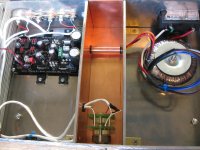
Alpha Copper shield, teflon jacket, 3 x 22ga.. 2824/3. The stuff is fairly stiff but should keep RFI and EMI at bay. It is 24pf/ft. which might be too much for some applications but it still fairly low.Westend,
What kind of wire is that? Looks handy.
I picked up a partial reel at my favorite electronics surplus outfit, "Hole in the Wall Electronics".😀
shielded twisted pair.
Where do you connect the individual shields?
Are you using the twisted pair to carry the flow of both R & L?
Where does the Return current go?
What about crosstalk?
Where do you connect the individual shields?
Are you using the twisted pair to carry the flow of both R & L?
Where does the Return current go?
What about crosstalk?
Last edited:
Let's say I want to increase the PS caps of my Mezmerize. Could I run some wire (as short as possible of course but probably 2in. or so) from the +/- on the Mez to a perfboard with larger sized caps?
Just do it. Are you going to run it for Amperes? Are the diodes up to it?
What do you mean exactly 'for Amperes'? I have the 500/600ma hot rod...
The diodes are the 11DQ10.
I was thinking of using 2x15kuf.
- Home
- Amplifiers
- Pass Labs
- Building a symmetrical PSU B1 buffer