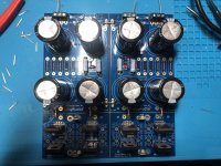
You have 0.47R in the bleeder resistor positions (R9,R10), so you essentially have a short to ground. Remove them and replace them with 3K or 4K 3W.
Tossed a couple 10k in and everything is hunky dunky. Should I have more than 1 filter resistor?
Looks very nice!!
EDIT: One resistor is fine. If you really want to add something, grab the 0.47 ‘s you removed and add them in series with the other filter resistor. More resistance in this case is beneficial. (Currents are very low so the losses are negligible.)
EDIT: One resistor is fine. If you really want to add something, grab the 0.47 ‘s you removed and add them in series with the other filter resistor. More resistance in this case is beneficial. (Currents are very low so the losses are negligible.)
Last edited:
Thanks 6L6, this forum and your build guides have helped me down the rabbit hole of this hobby. I am really enjoying it!
Intermittent input signal HELP!
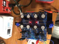
There have been a few instances in which the left channel loses gain and produces a kind of a motorboating hum. I wiggle the input leads and it goes away, everything ok. Then I might have the same issue whenever I start it up in the next listening session. I have done the left channel input connections twice already, disconnecting the leads, cutting 1 cm of the lead in case there was a nick, and re-soldering. Done this twice, last time half an hour ago. And, had to wiggle the leads.... Now sounding beautifully.
So I think there might be something going on with the soldering eyelet, maybe it is doing some kind of insidious contact in the bottom of the board with a solder run- I solder these on the top- What would you suggest if this keeps
happening.... Thanks!
Pass DIY Addict
Joined 2000
Paid Member
A few of the solder points on the bottom of the board that are rather large and will wick away heat from your soldering iron faster than the iron can provide heat. This results in a cold solder joint. You may need to leave your soldering iron on for an extended time to thoroughly warm the solder pads and the copper that is connected to them, or use a higher wattage soldering iron.
An open ground will produce the sound you are hearing.
An open ground will produce the sound you are hearing.
Have a question on R20. I am using an ortofon bronze MM cart. Do I install a 47k in R20 or leave open?
I'd say no. Wayne specified electrolytics be 35V unless specified, which for the Silmics is 25V.
Have a question on R20. I am using an ortofon bronze MM cart. Do I install a 47k in R20 or leave open?
You’ll leave it open, as the 47k is accomplished with the resistor next door.
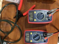
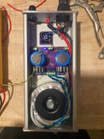
Assembled the PSU PCB in the Hammond case... measures +/- 31V on the output which is good. Makes for a nice compact PSU.
Still haven't connected to the Pearl boards yet, which I haven't built yet.
Love this PSU. Perfect use of space!
Power supply issues
I've built up my power supply for the Pearl 2 (based on 6L6's schematic) but have discovered an issue. The no load outputs are measuring +40.4Vdc and -40.3Vdc. I'm planning on using the AMB labs sigma 78 and 79 low noise regulators in my Pearl 2 build which can tolerate a maximum input of 35Vdc.
My power supply uses a 15VA Amgis L01-6355 transformer with dual 22Vac secondaries. The root cause of the issue is that (and I should have read the datasheet) the no load output of this 22Vac transformer is 27.2V, based on an input of 115Vac. Given that my mains voltage is sitting at 123.3Vac I'm seeing 28.7Vac at the secondaries. Converting this to DC gives me (28.7 x 1.414) 40.6Vdc.
Given that the Pearl 2 has a pretty low current consumption (~30-60mA I believe with the lower value on the -ve rail) I don't see the power supply output voltage under load dropping very much. I've ordered some resistors to load up the outputs and verify what voltage drop I can expect.
My question is how best to drop my output to below 35Vdc so I don't fry the regulators. The two options as I see it are as follows:
1. Replace the transformer with the L01-6354 which has 2 x 18V secondaries with a no load voltage of 22.2V. With a primary supply of 123Vac I figure I should get a no load output of 33.6Vdc.
2. Increase the value of the resistors in the CRCRC filter to drop the necessary voltage. And unless my math is wrong, in order to drop 6V at 20mA I would need a total resistance of ~300ohms in the -ve rail, and ~100ohms in the positive rail to drop 6V at 60mA.
Option 2 would be cheaper, but is it appropriate/reliable?
Thanks for your help in advance.
Gary
Pass DIY Addict
Joined 2000
Paid Member
I would wire it all up and see what happens you actually place a load on the transformer. With a 15VA transformer, it will sag a bit under any load. I used an Antek 25VA 25v transformer with a CRC filter to knock down a few volts. I think I used 10R 3w resistors. If you are concerned about blowing your regulators, install a CRC first and see what kind of voltages you get. Then you can tweak things from there.
Adjusting voltages with resistors in this case is simple because the current draw is so low.
Adjusting voltages with resistors in this case is simple because the current draw is so low.
- Home
- Amplifiers
- Pass Labs
- Building a Pearl 2