Current in those wires is stunningly high, because the diode conduction angle is much much less than 180 degrees. In other words the waveform of the current is a flatline zero milliamps, plus very narrow and very tall spikes every 8.33 milliseconds. The math is easiest if you assume the current spikes are well approximated by isosceles triangles, whose width is (conduction angle / 180) and whose peak is (1/width) times the DC load current.
The conduction angle is so narrow because the bulk filter capacitance is so big. The peak is so tall for the same reason.
And since editing the PCB artwork costs nothing, you get nonzero benefit for zero cost. Easy decision.
The conduction angle is so narrow because the bulk filter capacitance is so big. The peak is so tall for the same reason.
And since editing the PCB artwork costs nothing, you get nonzero benefit for zero cost. Easy decision.
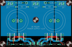
You can fill those three copper pour areas with both red and blue layers ... perhaps the red fill zone needs a little more clearance at its bottom edge. But otherwise you certainly do want both layers, ESPECIALLY connecting the "COM" pins of the two electrolytic caps together, around the top and bottom of that hole in the pour where an attachment bolt goes. You want the COM-to-COM path to have zero point zero zero milliohms of copper resistance.
Thanks for the feedback Mark. I filled those pours on both sides and additionally moved the hole in the center of the board south (to where the text is now), so that it isn't directly in between those two cap pins.
Gathering Parts for Pearl 2 to go with Korg B1 and F6
Hello,
Happy new year! I hope everyone is safe and well. I am building Pearl 2 and gathering parts. I bought 20 2sk170bl from the "trusted" seller from the Northern Cal. And the Idss measurements are as follow,
6.94 7.02 7.05 7.23
7.41 7.63 7.65 8.34
8.49 8.77 8.94 9.06
9.24 9.79 9.8 9.83
9.85 10.58 10.63 10.67
I plan to use the first 12.
Would that work?
Then I will save the rest for the future or spare for the pearl 2 and F6.
Thank you!
Power supply in same chassis - some progress
By internal shielding of the Pearl boards, I have made some progress, in my efforts to make a compact Pearl 2 with power supply inside the same chassis as the boards. The capacitive coupling between the mains power connector and the boards appeared to be the larger issue.
I did measurements of the output spectrum with no input signal attached. The input is loaded by 47 kOhm (first figure) and 237 Ohm (second figure). If 10 dB is added to the curves, then 0dB corresponds to 1V RMS.
From the second figure some 50Hz is still buried in the noise, but at a low enough level (<0.1mV)
In case anyone will redo the measurements for comparison. I should mention, I used 2 pcs. K369 for first stage and 2 pcs. K117 in second stage. The third figure is the noise floor of sound card.


Out of curiosity I also did a couple of distortion plots. The only output load is the sound card:
Input at @ 0.5mV RMS

Input at @ 1mV RMS

Input @ 2.5mV RMS input

By internal shielding of the Pearl boards, I have made some progress, in my efforts to make a compact Pearl 2 with power supply inside the same chassis as the boards. The capacitive coupling between the mains power connector and the boards appeared to be the larger issue.
I did measurements of the output spectrum with no input signal attached. The input is loaded by 47 kOhm (first figure) and 237 Ohm (second figure). If 10 dB is added to the curves, then 0dB corresponds to 1V RMS.
From the second figure some 50Hz is still buried in the noise, but at a low enough level (<0.1mV)
In case anyone will redo the measurements for comparison. I should mention, I used 2 pcs. K369 for first stage and 2 pcs. K117 in second stage. The third figure is the noise floor of sound card.
Out of curiosity I also did a couple of distortion plots. The only output load is the sound card:
Input at @ 0.5mV RMS
Input at @ 1mV RMS
Input @ 2.5mV RMS input
Last edited:
....Actually I think a good part of the distortion in the last plot stems from exceeding the sound card input levels, so disregard that figure. The Pearl 2 shouldn't be blamed for that.
Progress build picture 2
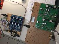
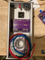
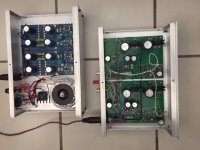
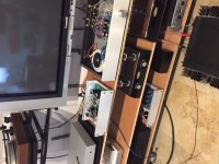
I had to breadboard the project though the enclosure shipment has been stuck in NJ since the 11th. without any new tracking report...
The AL angles I guess are to simulate the metal enclosure to connect grounds...
I already tested the power supply +31 and -31V. Tomorrow I will connect and see.
And....happy that got my first Covid19 shot yesterday....get vaccinated!!!
Attachments
@Manolo47 -- ya know, some of those Par Metal folks in Linden NJ are probably all from Portugal, your neighbor! That area of NJ (Newark, Linden, Union) have a very large population from Portugal and Brazil.
Pear 2 working!
The breadboard is done. Installed it and it worked fantastically well... the first time, no hum or noise, etc..so far. Offset voltage was a snap.
It has a little bit less gain than the Schiit Mani a nd the ZYX Artisan I have on loan. It looks like it will never offend, very smooth sounding so far. I know it will get much better after 50 hours or so. Thanks to Wayne for the design effort and to Jim for his enthusiasm and help!
Attachments

I had to breadboard the project though the enclosure shipment has been stuck in NJ since the 11th. without any new tracking report...
The AL angles I guess are to simulate the metal enclosure to connect grounds...
I already tested the power supply +31 and -31V. Tomorrow I will connect and see.
And....happy that got my first Covid19 shot yesterday....get vaccinated!!!
My wife returned a package in mid-Nov and it just arrived back at the seller. Mail is a mess. Build looks good though! I find mine has huge gain, when using a headamp I have to put the Pearl 2 on the low gain setting with a .2mV cartridge.
35A Bridge question, connection to chassis and circuit ground...
In the power supply schematic for the PS, this bridge is connected to both chassis and circuit grounds. However, I cannot see any apparent connection to the circuit ground in any of the construction photos and in 6l6'S
wiring schematic for the 2 cases. Thanks!
In the power supply schematic for the PS, this bridge is connected to both chassis and circuit grounds. However, I cannot see any apparent connection to the circuit ground in any of the construction photos and in 6l6'S
wiring schematic for the 2 cases. Thanks!
Take another look at the photos in post 1.
In the "bird's eye" photo of the power supply the wire is there but perhaps hard to see because it's black.
Is that what you're looking for?
In the "bird's eye" photo of the power supply the wire is there but perhaps hard to see because it's black.
Is that what you're looking for?
Power supply design...
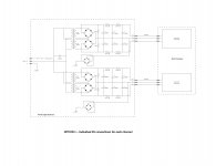
While getting stuck into the build of my M2X I started to think about the Pearl 2 parts I have stashed in the corner and how I am going to put together the power supply for it. I plan on putting the Pearl 2 into 1U slimline enclosure to match the BA2018 line stage I just finished, and ultimately want to have a separate PSU for it in a similar format chassis. The height available (40mm) limits the size of transformer I can put in there. So I got to thinking, why couldn't I use two separate transformers, one for each channel?
Reading Wayne's original article he mentions that it needs 28-34Vdc at 100mA. I'm assuming that's 50mA per channel. Based on that, is there any reason why I can't use (for each channel) a 15VA transformer with dual secondaries, each secondary rated at 22Vac, 380mA?
Assuming that will work, my next question is should I keep the 0V for each channel separate, or should they be tied together?
And lastly (for now), I believe I read that the power supply chassis should not be directly connected to the chassis of the Pearl 2. What about the chassis of the Pearl 2? Should it be tied to the Ov of the DC supply? I obviously want to make this as quiet as I possibly can, but still shoe-horn it inside a 1U enclosure. I hope the two attached sketches help make sense of my ramblings.
Thanks,
Gary
Attachments

There is no reason to build a dual mono supply.
A single 15VA transformer with dual secondaries is what I used.
Anything above 28V after the filtering caps is a vaste. The regulators should do fine with 26V according to datasheets.
You must connect the ground wire of your turntable to the chassis of the Pearl 2, and make some connection between the chassis and the Pearl 2 GND. But, maybe not tie them completely together. I used 12Ohm parallel with 100nF between Pearl2 GND and chassis.
Last edited:
The negative side draws only 25-30mA, the positive side 60-65ma . Do note that the poz side is feeding some mightily hungry caps for some milliseconds, then settles down.
I went ahead and produced a few of these PCB's that fit into a Hammond case.
They allow for the filter caps, LED's, CRC snubber and terminal blocks.
Using one should make easier work to build a compact Pearl 2 PSU that can be placed on the ground or a shelf away from the Pearl PCB's.
I still haven't populated and tested one so no guarantees (yet), but feel free to PM me if you're interested to use one.
Attachments
4 pin XLR connectors for umbilical PS
I am about to use these in my final stage of the project but I am not sure if these are ok for this purpose, I am getting some strange continuity between chassis and pins. Is there anything special I should do for the wiring connection, any specific pins?
I am about to use these in my final stage of the project but I am not sure if these are ok for this purpose, I am getting some strange continuity between chassis and pins. Is there anything special I should do for the wiring connection, any specific pins?
Finished!
Soundsing great!. Now that it is in final "housing" I can really say how it sounds. Very smoooooth, quiet, great harmonics and lightning fast.
Gain is really less than what I expected. Cartridge is an AT AT-F2, MC with a voltage gain of 0.32, rather low.
I guess I have to do something about the input and output wiring. The inquiry in the previous post regarding the 4 pin XLR is moot...inconsequential.
Attachments
Soundsing great!. Now that it is in final "housing" I can really say how it sounds. Very smoooooth, quiet, great harmonics and lightning fast.
Gain is really less than what I expected. Cartridge is an AT AT-F2, MC with a voltage gain of 0.32, rather low.
I guess I have to do something about the input and output wiring. The inquiry in the previous post regarding the 4 pin XLR is moot...inconsequential.
What value did you use for R14? Mine has tons of gain with R14 at 300R.
- Home
- Amplifiers
- Pass Labs
- Building a Pearl 2