@Manolo47
I got to thinking...Tea-Bag makes a raw power supply board for the Salas UltraFSP that would be ideal for a Pearl II build. I inquired with him and some are available, plus he has parts kits available for them as well. PM Tea-Bag.
I got to thinking...Tea-Bag makes a raw power supply board for the Salas UltraFSP that would be ideal for a Pearl II build. I inquired with him and some are available, plus he has parts kits available for them as well. PM Tea-Bag.
With respect to power supplies -- whether you use the on-board LM7824/7924 or a Salas, or Jung/Didden or Sulzer etc the output noise with the input shorted will be the same.
You’re not following me...it’s a raw power supply board that feeds the the Salas FSP which has on board regulation as well.
Can the UltraFSP board be made into a bipolar power supply? I don’t remember off hand... FSP is dual single-rail, not bipolar.
LM7824ct and lm924ct regulators difficult to find...
neither Mouser or Digikey has them. Mouser says that Lm924ct is obsolete...
Any suggestins will be appreciated
Thanks
neither Mouser or Digikey has them. Mouser says that Lm924ct is obsolete...
Any suggestins will be appreciated
Thanks
There are other +/-24V regulators in TO220 packages available, for example,
MC7824 and MC7924.
MC7824 and MC7924.
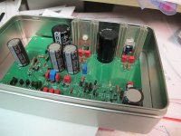
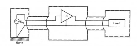
Fella in California selling "rectangular tin boxes" via EBay -- will have to use lower heat sinks, but the Pearl PCB will fit nicely inside and provide more magnetic shielding. Also reposting the illustration from a Linear Tech application note on low noise amplifier shielding:
Attachments
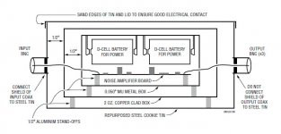
I wonder why the DUT is connected to the shielding boxes via conductive aluminium standoffs?
Looking at this multi-layered approach makes me wonder how Tom Evans' "Faraday cage" made up of copper sheets on either side of the signal boards managed to do anything at all? His "Groove" was celebrated for its quietness.
Looking at this multi-layered approach makes me wonder how Tom Evans' "Faraday cage" made up of copper sheets on either side of the signal boards managed to do anything at all? His "Groove" was celebrated for its quietness.
I wonder why the DUT is connected to the shielding boxes via conductive aluminium standoffs?
will see how it works -- I have both aluminum and nylon standoffs.
Attachments
That reminds me...
Marshall W. Leach put a ground all around the perimeter of his boards and tied these to the chasis.
I wonder... before the days of ground planes and mult-level boards perhaps his configuration was intended to help shield the circuitry. Maybe a loop of grounded conductor in the same plane as the circuitry would be a useful element to include in our designs.
I have an amplifier for DX'ing -- it came from the book "Receiving Antennas for the Radio Amateur" with a guard ring around the non-inverting pin of the op-amp, and have seen this often in data sheets for precision opamp allplication, but I don't know the merit of Dr. Leach's method.
We're amateurs, gotta try and see. My intent is to figure the best deployment of Wayne's boards to limit magnetic interference from transformers and power supplies.
We're amateurs, gotta try and see. My intent is to figure the best deployment of Wayne's boards to limit magnetic interference from transformers and power supplies.
The enclosure is plexiglas so not doing much in the way of shielding.
I was thinking of trying this idea with a Pearl 1 project.
It occurred to me that since you are doing up a new board for the mini Pearl II you could easily include Leach's idea (I'd be tempted to keep this ground "fence" separate from the signal and power supply grounds).
Last edited:
The "mini Pearl" is going to require some significant adjustment of component values to get it to work at the max Vds of the specified JFETs, but in some respect it can be made a bit better. Not rocket science.
In the interim, for all those who have Wayne's boards there's a fix for the EMI issues.
In the interim, for all those who have Wayne's boards there's a fix for the EMI issues.
Voltages sheet needed
I need the sheet that lists the proper voltage readings taken at various test points of the Pearl 2 circuit board. I’ve loaded it previously but can’t put my hands on it now. If anyone knows the link please post it. I’ve apparently done some damage to my Pearl 2 while hooking up a new turntable and need to track down the problem. I’m afraid I did an RCA connection with power on. Thanks.
I need the sheet that lists the proper voltage readings taken at various test points of the Pearl 2 circuit board. I’ve loaded it previously but can’t put my hands on it now. If anyone knows the link please post it. I’ve apparently done some damage to my Pearl 2 while hooking up a new turntable and need to track down the problem. I’m afraid I did an RCA connection with power on. Thanks.
"Chassis ground" connection in wood enclosure
The chassis grounding issue has been considered here and it looks like it is a part of the design, or at least very important.
If one is considering a wood enclosure, or at least abread board one during construction and testing phase, do I omit this or use an aluminun foil to connect these grounds... Thanks
R12 VALUE 909 OR 990R?
in the CB it says 909 and in the BOM I downloaded 990, which is correct? I ordered the 990 value. Would this be significnt?
Thanks.
in the CB it says 909 and in the BOM I downloaded 990, which is correct? I ordered the 990 value. Would this be significnt?
Thanks.
See post 1341 in this thread. With 990 you can get the RIAA correction closer to ideal, but you will also have to change some capacitor values. 0.11 uF for C10,11 and 14 combined (just leave out c10 or c11) and 0.32uF for c17-c20 combined (change c20 to 0.02 or 0.022).
Personally I preferred the ever so slightly fuller sound of the original.
Personally I preferred the ever so slightly fuller sound of the original.
- Home
- Amplifiers
- Pass Labs
- Building a Pearl 2