The sound fidelity issues seem to be C9 and C15. What part numbers are people using for these capacitors?
Part numbers? If you mean values, then based on measurement of RIAA curve I've used 15pF total. But I'm not done trimming.
I've had a little surprise. Toroidal transformers are not magnetically symmetric.
When I rotate the transformer around its axis of rotation symmetry, then with the location in the build I've shown above, I can find a direction where there is very very little hum and others where it is gradually more and some where it is too much.
I've tried with two different transformers from different manufacturers and the lead connections end up in the same corner for minimum hum.
I know I'm a bit naive placing a transformer close to a circuit with several hundred times of gain, although with proper transformer orientation it seems OK. Now I have confirmed and admit in full public, I'm also so dumb I thought toroidal transformer angle didn't matter.
No worries! We are all here to learn. 
The transformer trick is a good one, and you can go through all your components and try it to find the null.
The transformer trick is a good one, and you can go through all your components and try it to find the null.
CentralCoast - Your sound issues almost certainly have noting to do with the feedback lead compensation capacitor(s). I suspect that was what Pico was alluding to with his remark...
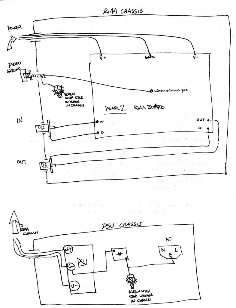
Can you post a couple of photos of your boards, PSU and outline your chassis connections?
They should follow this as closely (considering your batteries) as possible -
Can you post a couple of photos of your boards, PSU and outline your chassis connections?
They should follow this as closely (considering your batteries) as possible -
I have some replacement capacitors from your BOM on the way. I will rewire the grounding scheme and report back.
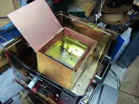
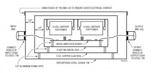
This is the shielded box I used to measure noise, and an illustration of the shielding technique suggested by Linear Tech (now Analog Devices) in an application note (I don't have a muShield box, so used a smaller cookie tin) -- I can measure as low as 420 pV/Rt Hz which is 60dB lower than the average MC cartridge, using Sam Groner's 60dB LNA
Attachments
I found the application note, and the Sam Groner LNA thread. Thanks for heads up. I should be able to make such a box.
I'm struggling a bit with the noise performance in relation to rtHz.
I understand why we get to V/rtHz from the thermal noise of a resistor.
How can we use a 420 pV/rtHz performance measure in relation to equipment without stating a bandwidth? Maybe I'm overthinking it. Thanks again 🙂
I'm struggling a bit with the noise performance in relation to rtHz.
I understand why we get to V/rtHz from the thermal noise of a resistor.
How can we use a 420 pV/rtHz performance measure in relation to equipment without stating a bandwidth? Maybe I'm overthinking it. Thanks again 🙂
How can we use a 420 pV/rtHz performance measure in relation to equipment without stating a bandwidth? Maybe I'm overthinking it. Thanks again
Getting a bit OT, but.....No, you aren't overthinking it at all. I became intrigued with Walt Jung's noise measurements in a 1995 article on regulator noise, and we have one of the real noise gurus as a participant in DIYaudio! I went down the rabbit-hole head first.
Let's say you are limited to a sound-card measurement system with a range of 20Hz to 20kHz and a really good low noise amplifier (LNA), but not an ultra good LNA. For me, the AD797, LT0128 or SSM2019 work fine, each will get you get you better than 1nV/RtHz. the designs by Sam, Gerhard and others take it almost order of magnitude better.
An FFT has to be adjusted for the bin size and the particular windowing methodology to get the bandwidth under measurement. Just running an FFT isn't going to solve it. To determine the V/RtHz you can run a test with a 1K resistor and 10k resistor to baseline the FFT. Each of these will exhibit noise, in volts per root Hertz of 4.0 and 12.7nV/RtHz. This works in the "white noise" region, so pick 1kHz and 10kHz. So download the data into Excel and work out your own equalization curve. If you're fortunate, you may have a spectrum analyzer which has selectable bandwidth!
As it pertains to the topic at hand, I am bothered that the original design is so hyper-sensitive to hum and the 120 and 360 Hz artifacts. It's a really nice design and easy to implement and it IS NOT noisy!!! The boxes I show above reduce 60Hz and 120Hz (50 and 100) hugely, and that was the point of my illustration.
I think it makes sense to me now. Thank you for clarifying.
When I get the Pearl 2 finished I will try to do the measurements. That would be the real test if I have understood things correctly. Back to topic (and apologies for putting the thread a bit off topic).
When I get the Pearl 2 finished I will try to do the measurements. That would be the real test if I have understood things correctly. Back to topic (and apologies for putting the thread a bit off topic).
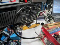
Here are some photos of my rewired boards. I have followed the 6L6 grounding scheme and isolated the power ground from chassis. I have also isolated the input and output grounds as indicated in the suggested wiring diagram. After replacing C9 with a MLCC 5pF C0G ceramic cap, it sounds a bit better but everything is still mostly washed out with static still. Should I remove C9 for a MM cartridge?
I have gone thru and verified voltages, impedances, etc. Drain to source impedance using my DMM across Q6 is only 16ohms? I don't see how that could be right??
Any suggestions appreciated!
Power input +-39VDC from a battery is via the XLR jack. The DC jack is for the "signal ground pad" ground wires. I have tried them floating and tied to chassis without a difference. There is no ground wire or terminal on the Rega Planar 2 turntable, so I have not connected it to the TT. The Rega Planar 2 does not use a ground connection, and I have tried tying the chassis of the Pearl 2 to the house socket earth ground, without any change.
Both channels exhibit the same noise characteristics.
I soldered the components from the reverse side. Should I touch them up on the top side? Any risk of not connecting to a trace if the top is not soldered nicely?
I am using a Grado XC+ MM cartridge.
Please open the image links in a new tab to view. Seems like I have not mastered adding images.
An externally hosted image should be here but it was not working when we last tested it.
An externally hosted image should be here but it was not working when we last tested it.
An externally hosted image should be here but it was not working when we last tested it.
An externally hosted image should be here but it was not working when we last tested it.
An externally hosted image should be here but it was not working when we last tested it.
An externally hosted image should be here but it was not working when we last tested it.
Last edited:
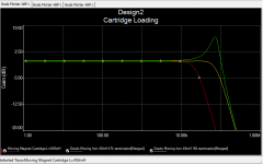
If I am not mistaken, Grado XC+ is a moving iron cartridge with 5mV output. Two things have to change. The cartridge loading resistor (R19) at 47k will under-damp the response. This results from the low inductance of 45mH (moving magnet carts are 10x this value). Thus the loading resistor may be less than half the 47k.I am using a Grado XC+ MM cartridge.
Second, with 5mV output chances are that you are overdriving the output stage.
Third, I believe that the upper limit for the input voltage LM7824/7924 is +/-38V. TI no longer has a data sheet on their website, and the product is not in the "National Semiconductor Power IC's Databook"
What do you suggest to resolve overdriving the output stage? Changing R14? Do you have a suggested resistor value for R14?
I updated so that R19/R20 in parallel are 16K. I also changed R16 to be 50Kohms. The sound issues are mostly resolved. There is still a bit of noise/harshness in the high frequencies. I'll keep playing with R16 and R19 to try to resolve. Any other suggestions? I appreciate the help! Thank you.
You mention it’s a Grado XC+, that’s a pretty old cartridge... I remember chasing an issue with a turntable, really banging my head because some issues just wouldn’t go away, and it ended up being nothing more than all of my cheap & cheerful test cartridges were worn out.
Also, what are you using for cartridge alignment. ?
I am not disagreeing with the possibility of overloading the input, jack has shown that it’s possible. But I’ve used some pretty hot cartridges over the years and never heard it with the Pearl 2.
Also, what are you using for cartridge alignment. ?
I am not disagreeing with the possibility of overloading the input, jack has shown that it’s possible. But I’ve used some pretty hot cartridges over the years and never heard it with the Pearl 2.
Maybe another possibility: I see you have C7 mounted. Mine had high frequency instability until I removed it. I think it is recommended to not mount it somewhere further back in the thread. I use 2sk117 in the second stage. They have a smaller input capacitance than 2sK370. I don't know if that plays a role
You mention it’s a Grado XC+, that’s a pretty old cartridge... I remember chasing an issue with a turntable, really banging my head because some issues just wouldn’t go away, and it ended up being nothing more than all of my cheap & cheerful test cartridges were worn out.
Also, what are you using for cartridge alignment. ?
I am not disagreeing with the possibility of overloading the input, jack has shown that it’s possible. But I’ve used some pretty hot cartridges over the years and never heard it with the Pearl 2.
Using the Parasound Zphono pre-amp, I don't have a problem with my cartridge. I am open to purchasing a newer model. Do you have a suggestion for something in the $75-$150 range? Also, any modifications to the Pearl 2 for suggested cartridge would be helpful.
I have not aligned the cartridge, but I will look into it.
I have removed C7 and it seems to be much cleaner. I will continue testing, but that might have finished solving the issues.
Last edited:
To demo the importance of proper shielding and grounding I ran this test. My LNA is Sams 8x BF862 from Linear Audio, gain of 60dB and noise ~425-460nV/Rt Hz. As sanity test I shunt the input with a 60 ohm resistor, which should be a bit greater than its thermal noise owing to the amplifier.
The "ugly" data were taken with the amplifier shielded, but the shield disconnected from the AP analyzer. The "nice" data the cookie tin used for shielding is connected to the analyzer. Its 33 to 50x better.
By the way, Wayne's boards WILL fit in the rectangular Oreo Christmas Cookie Tin.
The "ugly" data were taken with the amplifier shielded, but the shield disconnected from the AP analyzer. The "nice" data the cookie tin used for shielding is connected to the analyzer. Its 33 to 50x better.
By the way, Wayne's boards WILL fit in the rectangular Oreo Christmas Cookie Tin.
Attachments

By the way, Wayne's boards WILL fit in the rectangular Oreo Christmas Cookie Tin.
I love the cookie tin! A couple decades back I was performing sensitive electrochemical impedance spectroscopy measurements that were measuring magnitude and phase angle of nano-amp level signals. I was using an old metal lunchbox as my faraday cage holding the electrochemical cell sitting next to about about $100k worth of measurement gear. Everybody thought I was nuts, but all you had to do was open the lunchbox lid a crack and watch the EM pollution swamp the signal.
Simple solutions work!
- Home
- Amplifiers
- Pass Labs
- Building a Pearl 2