The DC offset. I’m measuring it by putting one probe on the DC offset hole and the other on a ground pad. Without playing a record and nothing on input, the offset can wander over time from 0 to + or - 100mv. Is that too much drift?
That level of DC offset is normal and isn't a problem if you have C13 installed. If you want to improve on that Wayne has advised you can install a capacitor in series with R14 in the 47-470 uF range with an optional film bypass capacitor. I put a 220uF Silmic cap here with a 0.1uF film bypass, and my DC offset dropped down to +/- 1mV. With that you could short C13 to eliminate the output cap.
Cheers,
Terry
I see takitaj beat me to it after I posted. Good advice bears repeating I guess.
Oh maybe I shouldn’t be measuring at that test point and instead after the output capacitor and what the preamp is seeing. If I measure from the + out and GND out then it’s much much more stable. Now that I think about it, that’s where I’ve always measured offset on other builds so that makes sense.
I’ll try the capacitor mod after I measure it a bit more after it’s been warm and see if I need it.
On a side note, I was reaching behind my turntable and my shirt must have caught the needle and bent it, the broke it. Rookie move.
I’ll try the capacitor mod after I measure it a bit more after it’s been warm and see if I need it.
On a side note, I was reaching behind my turntable and my shirt must have caught the needle and bent it, the broke it. Rookie move.
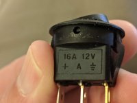
LED Question
I noticed that when I use 350 ohms for R14 to raise the gain for low output MC cartridges, LED1 becomes dimmer than when R14 = 1K. Is this normal?
I noticed that when I use 350 ohms for R14 to raise the gain for low output MC cartridges, LED1 becomes dimmer than when R14 = 1K. Is this normal?
Adding a SE to Balanced output circuit to a Pearl 2
New to the forum... and there is a lot to read up on!
I'm planning on a summer Pearl 2 build (if I don't do a F4 first) and am pulling together my plan. My system is balanced throughout and I was wondering if anyone has thoughts on the best circuit to take the SE out of the Pearl 2 PCB and convert to balanced before an XLR output.
Thanks!
Rob
Use a 1;1 transformer on the front end and a ThatCorp 1646 balanced line driver on the output. THAT Corporation 1606/1646 OutSmarts Balanced Line Driver ICs
Sparkfun has a cute little 1646 board and a very good article page -
THAT InGenius and OutSmarts Breakout Hookup Guide - learn.sparkfun.com
THAT InGenius and OutSmarts Breakout Hookup Guide - learn.sparkfun.com
Probably should put some protection diodes on the 1646 input as there is (briefly) DC on the output of the Pearl 2.
In fairness to TI and ADI, they also make some nice line drivers.
In fairness to TI and ADI, they also make some nice line drivers.
Do you sacrifice any performance if you convert unbalanced to balanced?
Also, can you use the Meanwell power supply offered at the Diy Store (or something like it) for the each board of the Pearl?
Also, can you use the Meanwell power supply offered at the Diy Store (or something like it) for the each board of the Pearl?
Pearl 2 build with adjustable input loading and gain
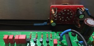
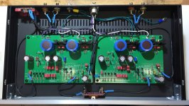
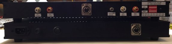
My Pearl 2 is done and sounds great! Vinyl has never sounded this good to me. No problems with either the added rear panel DIP switches for input loading or the front panel 3 position gain switch.
Upon initial testing, ultrasonic oscillation was observed on the scope, severe enough to cause motorboating in the right channel at the highest gain setting. Per suggested forum posts, capacitor C7 was removed from the circuit in both channels and this resolved the oscillation issue.
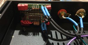
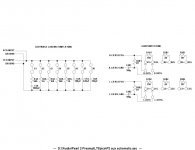
The adjustable front panel gain switch, SWB, is a 4-pole 3-position switch that connects at the R14 position on the main PCB. It includes a constant 2K ohm load on the switch output to allow the break-before-make switch to be operated under load without removing all resistance from the R14 position in the circuit. Per suggested forum posts, the ground side of the R14 circuit has been AC coupled using a 100uF 63V Nichicon audio grade electrolytic cap.
With input loading switches at their default termination settings (47K/100pF) and no turntable connection, no hum or buzz was observed in the loudspeaker system at gain levels 48dB and 55dB, even with the RIAA unit placed directly on top of the PSU. At the highest gain level, 65dB, an extremely low level hum was present that reduced a bit when properly allowing good space between the PSU and the RIAA chassis. It completely disappeared when any of the resistive input load switches were engaged.
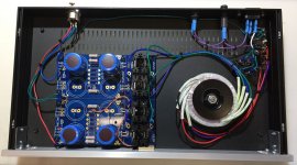
The quiet might be those steel chassis covers and some extra gounding I did to the RIAA chassis. I added a ground lug to the bottom panel. I did take care to remove some anodizing from the rear, sides and front panel joining surfaces to allow ground continuity to every part of the chassis except the top cover. I may go back and do that one as well. The bared mating surfaces were lightly coated with Cramolyn Red before assembly to help prevent oxidization. One of the DeoxIT products would probably do the same job.
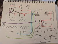
I'v included parts lists and schematics for my mods in case anyone wants to give them a try.
My Pearl 2 is done and sounds great! Vinyl has never sounded this good to me. No problems with either the added rear panel DIP switches for input loading or the front panel 3 position gain switch.
Upon initial testing, ultrasonic oscillation was observed on the scope, severe enough to cause motorboating in the right channel at the highest gain setting. Per suggested forum posts, capacitor C7 was removed from the circuit in both channels and this resolved the oscillation issue.
The adjustable front panel gain switch, SWB, is a 4-pole 3-position switch that connects at the R14 position on the main PCB. It includes a constant 2K ohm load on the switch output to allow the break-before-make switch to be operated under load without removing all resistance from the R14 position in the circuit. Per suggested forum posts, the ground side of the R14 circuit has been AC coupled using a 100uF 63V Nichicon audio grade electrolytic cap.
With input loading switches at their default termination settings (47K/100pF) and no turntable connection, no hum or buzz was observed in the loudspeaker system at gain levels 48dB and 55dB, even with the RIAA unit placed directly on top of the PSU. At the highest gain level, 65dB, an extremely low level hum was present that reduced a bit when properly allowing good space between the PSU and the RIAA chassis. It completely disappeared when any of the resistive input load switches were engaged.
The quiet might be those steel chassis covers and some extra gounding I did to the RIAA chassis. I added a ground lug to the bottom panel. I did take care to remove some anodizing from the rear, sides and front panel joining surfaces to allow ground continuity to every part of the chassis except the top cover. I may go back and do that one as well. The bared mating surfaces were lightly coated with Cramolyn Red before assembly to help prevent oxidization. One of the DeoxIT products would probably do the same job.
I'v included parts lists and schematics for my mods in case anyone wants to give them a try.
Attachments
-
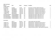 P2 AUX parts list.jpg103.3 KB · Views: 559
 -
 P2 SWB.jpg173.5 KB · Views: 337
 -
 P2 SWA rear.jpg212.3 KB · Views: 388
 -
 P2 RIAA.jpg273.2 KB · Views: 372
 -
 P2 Rear.jpg60.1 KB · Views: 377
 -
 P2 PSU.jpg237 KB · Views: 572
 -
 P2 Front.jpg78.4 KB · Views: 565
 -
 P2 PSU-A schematic.jpg65.2 KB · Views: 591
 -
 P2 AUX schematic.jpg50.1 KB · Views: 569
Very nice! I added the same switching options to mine, although I didn't add the resistor to keep R14 from going open while switching. What's the reason for the PS mods?
Wow that looks incredible. I’m super jealous.
Thanks for posting the pics of the dip switch and the gain selector.
What cartridge are you using and how did you set your gain?
Thanks for posting the pics of the dip switch and the gain selector.
What cartridge are you using and how did you set your gain?
Very nice! I added the same switching options to mine, although I didn't add the resistor to keep R14 from going open while switching. What's the reason for the PS mods?
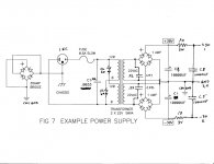
6L6 showed MUR diodes, 0.22 snubbers and CRC filtering in his primary supply design at the beginning of this forum. He also recommended replacing my original 0.47X4 (0.12R) between caps with 10 to 20 ohms between caps. I chose 20X2 (10R).
The idea is that a quieter primary supply would yield a super quiet supply downstream of the regulators on the main PCB. Given that I am accommodating a low output MC cart with a 10dB higher gain option that is at the limit of Mr. Colburn's recommendations, it seemed like a good idea.
The idea is that a quieter primary supply would yield a super quiet supply downstream of the regulators on the main PCB. Given that I am accommodating a low output MC cart with a 10dB higher gain option that is at the limit of Mr. Colburn's recommendations, it seemed like a good idea.
Most often snubbers are a solution looking for a problem. If there is no ringing there is no necessity.
While the LMxxx regulators are not the quietest, i could not see any noise using them or powering the Pearl with a Jung SR.
Wow that looks incredible. I’m super jealous.
Thanks for posting the pics of the dip switch and the gain selector.
What cartridge are you using and how did you set your gain?
I'm currently using a MM cart, an Ortofon super OM20 (on a Thorens TD-145 MKII turntable that I have owned since the late 1970s). Sadly, my old Goldring 900SE stylus bit the dust. I consider that one of the better MM carts ever made. The OM20 is a bit more clinical sounding but the Pearl opens it up in ways that do not include any harshness. Maybe the ability to fine tune input capacitance helps. I settled on 320pF (plus whatever is in the cables). I can't comment yet on any MI or MC carts.
Gain at the lowest (MM) setting was finalized at around 9dB higher than my Cambridge Audio Azur 551P MM phono preamp, which is specified at +39dB @ 1KHz. My thought is that +48dB is low enough to be a better match to downstream components yet can still accommodate lower output MM or even some MI carts. The Pearl circuit is certainly quiet enough, right on up to +65db of gain.
I suppose the potential for circuit overload with a very hot MM cart still exists but I'll cross that bridge if I come to it. If a cart really is that hot, perhaps an external resistor pad would be an option. But it seems that with higher end phono carts, the challenge is typically in accommodating lower output rather than higher output.
I have R14 selectable between 300, 600, and 1K ohm and it seems to accommodate pretty much any MM or MC cartridge. I actually have to turn the gain to the middle or lower setting with a LOMC going straight into an O2 phono preamp so as not to overload it.
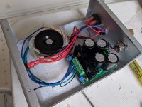
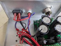
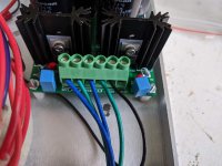
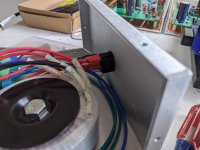
Finished wiring my power supply and upon turn on I blew the .5a fuse? Any ideas? Here's some pics of the build attached below.
Attachments
- Home
- Amplifiers
- Pass Labs
- Building a Pearl 2