Cartridge loading
Working my way through the Pearl 2 build and read the forum a couple of times over a 12 month period. I can get myself quite confused when reading what experienced DIYer's talk about. So my question related to cartridge loading for the Audio Tech AT33ev cart which is 0.3Mv, with a recommended load impedance in >100ohm. So is the value for R14=100 ohm; R14=100 ohm and R25 remain at 4.75K. Thanks, Andrew
Working my way through the Pearl 2 build and read the forum a couple of times over a 12 month period. I can get myself quite confused when reading what experienced DIYer's talk about. So my question related to cartridge loading for the Audio Tech AT33ev cart which is 0.3Mv, with a recommended load impedance in >100ohm. So is the value for R14=100 ohm; R14=100 ohm and R25 remain at 4.75K. Thanks, Andrew
General rule of thumb is to target a 1.0V output. For a 0.3mV cartridge output we need total gain of 3333x or ~70dB, which is 15dB more than the stock Pearl 2. The Pearl 2 stock second stage has 40dB gain, so we need to increase that to 55dB or 562x. The second stage gain is (R15+R16)/R14. So you could change R15 to 462k, or alternately you decrease R14 to ~178R (do one or the other, not both). That addresses the gain setting.
For the load impedance of >100R, that is set by putting in the desired load value into R20.
That being said, I’m not the most expert what the best gain and load setting are for a particular cartridge, and others might have better advice to fine tune what I’m saying here.
Cheers,
Terry
For the load impedance of >100R, that is set by putting in the desired load value into R20.
That being said, I’m not the most expert what the best gain and load setting are for a particular cartridge, and others might have better advice to fine tune what I’m saying here.
Cheers,
Terry
Now another perspective comes from the KAB Phono Preamp Parameter Computer (see here https://www.kabusa.com/pregain.htm ) which for a 0.3mV sensitivity cartridge recommends 58dB gain, which is pretty close to the 55dB gain of the stock Pearl 2. So we can also defer to 6L6’s excellent advise of build it stock and try it out first, and then mod it from there if it doesn’t do exactly what you want.
Terry
Terry
Thanks for the advice Terry. I just went back and had a look at the Pearl 2 build manual from Pass and things are falling into place. Thanks
Andrew
Andrew
Working my way through the Pearl 2 build and read the forum a couple of times over a 12 month period. I can get myself quite confused when reading what experienced DIYer's talk about. So my question related to cartridge loading for the Audio Tech AT33ev cart which is 0.3Mv, with a recommended load impedance in >100ohm. So is the value for R14=100 ohm; R14=100 ohm and R25 remain at 4.75K. Thanks, Andrew
The manual says to go to 300R in R14 for extra gain, I use an AT33PTG and find that amount of gain just right.
What is this
Looking through photos of the pearl 2 build I came across these terminals on R20 and was wondering if someone could tell what they are called, and if they could be used for trying different resistor values without having to solder the resistors to the board. Thanks
Andrew
Looking through photos of the pearl 2 build I came across these terminals on R20 and was wondering if someone could tell what they are called, and if they could be used for trying different resistor values without having to solder the resistors to the board. Thanks
Andrew
Attachments
Maybe they are breakaway SIP sockets like Mouser part number 437-3108716441001101
You break off as many or as few pins as you need; they are on a pitch of 0.1" (2.54mm) to match DIP and SIP integrated circuits.
Maybe that photo shows somebody who broke off just 1 pin ?
https://www.mouser.com/ProductDetail/Preci-dip/310-87-164-41-001101?qs=uQD7XCvsSCPvz1PkaTv0ZQ==
You break off as many or as few pins as you need; they are on a pitch of 0.1" (2.54mm) to match DIP and SIP integrated circuits.
Maybe that photo shows somebody who broke off just 1 pin ?
https://www.mouser.com/ProductDetail/Preci-dip/310-87-164-41-001101?qs=uQD7XCvsSCPvz1PkaTv0ZQ==
Mark is correct, breakaway SIP sockets. I used these: https://www.digikey.ca/products/en?keywords=2-1571994-0
I put them in for R15 and C15 positions to allow me to increase or decrease gain of the second stage, and for R20 to allow me to change the cartridge loading. Some people have also put them for C22 as well, but I’ve left that one with 100pF soldered in Place for now.
Terry
I put them in for R15 and C15 positions to allow me to increase or decrease gain of the second stage, and for R20 to allow me to change the cartridge loading. Some people have also put them for C22 as well, but I’ve left that one with 100pF soldered in Place for now.
Terry
Mark is correct,
You can set your clock by him!
I always use the SIP sockets for RIAA networks, whether the Pearl or His Majesty's Noise!
Be mindful of this, however. While conformance to the RIAA curve is quite important the match between channels is equal.
FYI the leads on the small size resistors don't have a big enough diameter for these. I also found they sometimes lose contact regardless after being installed for a while. That's why I went to switches.
Testing the Pearl 2
Need some assistance interpreting these measurements please.
V+ / Ground 31.93V
V- / Ground 32.09V
R4 / R33 47.9V
R4 / Ground 23.92V
R33 / Ground 24.10V
R6 = 1.4
Output= Unstable (5-22mV)
Measured with DMM x 1
Powered through Universal PSU 32VDC
Thanks, Andrew
Need some assistance interpreting these measurements please.
V+ / Ground 31.93V
V- / Ground 32.09V
R4 / R33 47.9V
R4 / Ground 23.92V
R33 / Ground 24.10V
R6 = 1.4
Output= Unstable (5-22mV)
Measured with DMM x 1
Powered through Universal PSU 32VDC
Thanks, Andrew
Those measurements all look pretty typical. The circuit draws less current from the negative supply rail than the positive, which explains the minor asymmetry in the readings. The output wandering around a bit is normal, unless you have done the modification of putting a cap in series with R14.
Pearl 2 testing as per schematic
Found the schematic as have been testing this morning.
Board 1 Board 2
R25 = -22.01 -22.05
Q1/R9 = 22.95 20.2
R8 = 10.92 8.7
Q3 12.5 8
10 8.6
10 8
Q6 -Q9 10V 8V
50mV 60mV
R28 - 22.71 -22.67
R29 -22.63 -22.61
R27 -22.1 -22.07
Unfortunately, none of these figures mean anything to me. They may be good or not so good, and therefore I am once again relying on the vast experience of the forum members to guide me in the right direction. All the best. Andrew
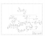
A better way will be to check the measurements that are identified in the attached schematic. This was posted somewhere back in this thread, but I couldn't quickly find it to link it, so I hope the forum will forgive me posting it again here.
All the voltages indicated in the schematic are measured referenced to ground. Don't expect your boards to measure exactly the same as the indicated voltages, as long as you are in the general ballpark you are ok, as the variation in parts values, especially from JFETs and MOSFETs will move things around a bit.
Terry
Attachments
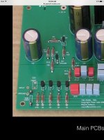
Here's the new build BTW!
Edit - was going to mention that the connections to the rotary switches are Belden microphone cable, with all the drain wires going back to the input ground. Once that was done it got nice and quiet. It has 3 gain settings, 5 resistive load settings and 5 capacitive settings including zero.


An update on my Pearl with switchable gain and loading - last night I switched resistive loading, and one channel thumped/burped and sent the receiver into protection mode. Upon checking the Pearl board the DC offset was wonky but other voltages were fine. It took a couple reboots of both the Pearl and receiver to get the channel to work again (phew!).
Lesson learned, change load settings only when powered off (changing gain setting doesn't bother it). Maybe better switches would prevent this.
I see your "Cat Master" guarding music room....would love (next time apart) to see close ups of your switching.
Russellc
I see your "Cat Master" guarding music room....
Russellc
He's 19 pounds of guard cat. Unfortunately he has developed a liking for speaker grills.
One thing I need to change is to wire the inputs/outputs next to each other instead of across the chassis, tonearm cables don't reach that far apart.
He's 19 pounds of guard cat. Unfortunately he has developed a liking for speaker grills.
One thing I need to change is to wire the inputs/outputs next to each other instead of across the chassis, tonearm cables don't reach that far apart.
I leave mine facing the wall when gone. Speakers are spiked, but I discovered the basic plastic feet the come with power amp chassis, with felt sliders stuck on bottom, allow me to move them around.
I had one cat that hearing the gentle hum of a tube amp through Altec A7, ran full speed and put a four foot death grip on a 515 8G cone....not once, but twice. Another removed the dust cover from a 416 8C. A7 now have protective screens.....
Russellc
Yea better the grills than the cones.
- Home
- Amplifiers
- Pass Labs
- Building a Pearl 2