That does look pretty minimal, it might be doable. Is that a 22v Antec in a Galaxy case? Looks great, by the way!
Yes 2x22v Antek in a Galaxy case. I used a proto-board from Allied and it worked great. If you need a BOM PM me.
Thanks! I will look into this because I am not good at reading a schematic and point to point wiring, although I am going to learn. I also think it might good experience if I want to build one of the First Watt amps when the jfets come back in stock. I'm going to take my time and follow the guide. Having more capacitance with the Universal PSU can't hurt, correct? I'll stick to standard reliable parts this time and when I learn more, I'll splurge on the higher end stuff. I am also going to start the Whammy headphone amp also (maybe I should do that first, seems more straightforward).
Any other advice is always welcome.
As far as the PSU is concerned, you can build it with relativley little capacitance without much difficulty.
Building the whammy isn’t such a bad idea - there are much fewer decisions to make re parts and settings and it’ll give you a good way to exercise your skills.
Hey all. Quick question. I'm in the process of ordering the parts from Mouser and Digikey. I can't really figure the part for R12? It's a 909 resistor? I'm working from the PDF that Wayne has on the site. Thanks. Also, for the power supply could I do dual transformers with the PSU power supply or is that overkill.
Thanks!
Thanks!
There was some discussion as to whether it was 909 or 990. I bought both values and am starting with 990. For more info read posts 970 and 971.
I've just ordered the last few pieces that I messed up from my original order. If all goes well it should be up and running in a week or two.
I learned a couple of valuable things regarding my bom. I need to pay more attention to the size of the components. The 10K uF caps I ordered were too big for the heatsinks next to them that I ordered which required trimming them. I also ordered larger resistors which required a lot of extra work bending leads to make them look neat. Otherwise the build has been pretty straightforward.
Good luck with your build!
Last edited:
Re: R12 = 990 or 909
Don’t sweat it too much. It makes about 1/5dB difference between 100 and 200 Hz. If you can reliably hear that then you have way better ears than me. I used 909 and mine sounds pretty spectacular.
Re: dual transformers / dual mono ps
Just be aware that the lighter loading of the trafos will result in the rectified rail voltages being higher and you might need to throw away some extra voltage before sending it to the preamp boards. It’s what I had to do. Yes, a dual mono power supply is overkill, but why not! You do get little better channel separation, and this is kind of a moon shot type of project.
Last edited:
There was some discussion as to whether it was 909 or 990. I bought both values and am starting with 990. For more info read posts 970 and 971.
I've just ordered the last few pieces that I messed up from my original order. If all goes well it should be up and running in a week or two.
I learned a couple of valuable things regarding my bom. I need to pay more attention to the size of the components. The 10K uF caps I ordered were too big for the heatsinks next to them that I ordered which required trimming them. I also ordered larger resistors which required a lot of extra work bending leads to make them look neat. Otherwise the build has been pretty straightforward.
Good luck with your build!
Thanks! You too!! Almost done with the order.
Re: R12 = 990 or 909
Don’t sweat it too much. It makes about 1/5dB difference between 100 and 200 Hz. If you can reliably hear that then you have way better ears than me. I used 909 and mine sounds pretty spectacular.
Re: dual transformers / dual mono ps
Just be aware that the lighter loading of the trafos will result in the rectified rail voltages being higher and you might need to throw away some extra voltage before sending it to the preamp boards. It’s what I had to do. Yes, a dual mono power supply is overkill, but why not! You do get little better channel separation, and this is kind of a moon shot type of project.
Thanks for the insight. I'll try 909 because 990 is out at Digikey and Mouser.
I'll investigate the dual mono some more. The power supply is still a head scratcher for me, but I will read 6L6 build guide.
Don’t bother with dual transformers. It will be a huge headache with no real benefit, and a very big chance to make things worse.
Don’t bother with dual transformers. It will be a huge headache with no real benefit, and a very big chance to make things worse.
Ok. That sounds like too much for me. I'll stick with a single transformer.
I have one last part of the Pearl boards to order and that is the heatsinks for the voltage regulators, can anyone point me to the correct one, it's not on the list?
Thanks
Sorry for the rookie questions, it's all new to me.
This was linked at the bottom of the LED product page when I was selecting them: 513201B02500G Aavid, Thermal Division of Boyd Corporation | Fans, Thermal Management | DigiKey
That does seem to be it but is 2" too big?
That does seem to be it but is 2" too big?
That's what I used but I also like the clip on heat sinks like the ones shown earlier in the thread.
A 10K and 1K paralleled will give you 990 I think I had 909 in stock for something and used it. A bit of a hump but perfect for many speakers😉
Hey Wayne - 10K and 1K paralleled is 909 unless I'm not calculating correctly.
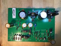
My second Pearl 2 build is nearing completion. I built the first set with the parts as recommended by the manual and ended up giving it to a friend. I built the next set using a “Formula 1” philosophy. All resistors except the 10Ω and 499Ω are 0.1% and the film capacitors are MKP 1837, which were a tight fit. The power supply has enough capacitance for a reasonably sized power amp, because, why not?
All four boards were completed without blowing a single ZVP device.
Here’s one of the boards and the capacitors trying to squeeze in:
All four boards were completed without blowing a single ZVP device.
Here’s one of the boards and the capacitors trying to squeeze in:
Attachments

Last edited:
Hey Wayne - 10K and 1K paralleled is 909 unless I'm not calculating correctly.
No you are correct.
My second Pearl 2 build is nearing completion. I built the first set with the parts as recommended by the manual and ended up giving it to a friend. I built the next set using a “Formula 1” philosophy. All resistors except the 10Ω and 499Ω are 0.1% and the film capacitors are MKP 1837, which were a tight fit. The power supply has enough capacitance for a reasonably sized power amp, because, why not?
All four boards were completed without blowing a single ZVP device.
Here’s one of the boards and the capacitors trying to squeeze in:
Very nice, which make/series of resistors did you use? Also wondering why you were blowing transistors?
The ZVP3310 in the output circuit is extremely static sensitive, about half of the builders have lost one durning normal careful assembly.
I'm on that list. 🙂
I'm on that list. 🙂
McQuade, the ZVP MOSFETs used in Pearl2 have a reputation for poor ESD tolerance among diyAudio builders. Many many people have observed this and reported it on the site. When you stuff and solder them, don't be shocked if they're dead before you ever power up the board. Standard practice is to buy 3X as many as you need for the Pearl2 board(s) you're building, just so you will have enough spares to replace the dead ones again and again, until the board stops failing and starts working.
Very nice, which make/series of resistors did you use? Also wondering why you were blowing transistors?
Black resistors are 1/4W 0.1% Welwyn Components / TT Electronics RC55 series brown are Dale RN60. To be homest, I got the black ones because they look really nice, look at Mouser part 66-RC55LF-D-1.0K as a random sample..
The transistor point was a cheap bragging opportunity, sorry. Having read this thread before the first build I was expecting to blow at least half of the ZVP devices as many people seemed to do due to its high static sensitivity. I was really surprised that I didn’t.
The transistor point was a cheap bragging opportunity, sorry. Having read this thread before the first build I was expecting to blow at least half of the ZVP devices as many people seemed to do due to its high static sensitivity. I was really surprised that I didn’t.
It's a common enough occurrence that you are allowed to brag a little if you didn't have any issues... 😀 😀 😀
- Home
- Amplifiers
- Pass Labs
- Building a Pearl 2