Nope.
Easy. 🙂
Thanks for the quick response, soon as I m done with BA-3 as pre, Im on to the Pearl finishing...having to wait for a BA-3 board to finish the BA-3 power amp, which I have everything else for😉
Russellc
Help needed with PSU
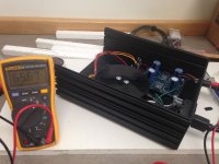
So today I finished wiring up the PSU for my Pearl 2. I switched it on, plugged in my DMM and got the reading below, in the picture, which is too high, right? But at least there were no sparks or smoke. A few hours later I tried it again, and this time only saw about 7 millivolts, and the fuse looks smoked, though still intact. What have I done?
So today I finished wiring up the PSU for my Pearl 2. I switched it on, plugged in my DMM and got the reading below, in the picture, which is too high, right? But at least there were no sparks or smoke. A few hours later I tried it again, and this time only saw about 7 millivolts, and the fuse looks smoked, though still intact. What have I done?
Attachments
So today I finished wiring up the PSU for my Pearl 2. I switched it on, plugged in my DMM and got the reading below, in the picture, which is too high, right? But at least there were no sparks or smoke. A few hours later I tried it again, and this time only saw about 7 millivolts, and the fuse looks smoked, though still intact. What have I done?
Thats not the same fluke as mine, but it looks like 65 volts to me, no? If you are measuring from V- to V+ thats about right. If thats the case, measure from either V- or V+ and ground. My fluke shows Mv if its millivolts...If thats the before pick, and you were measuring from V- toV+, mine shows about 60v dc. Make sure you are set to DC, and if from V- or V+ and ground and it says 7 mv, yeah something is wrong. If thats the case people here can help, but they will want clear pics of the build and so forth. Fuse still good?
Russellc
Last edited:
Yes, 65 volts. I will try a slo-blow tomorrow and see how it goes. It was stable before I started poking around.
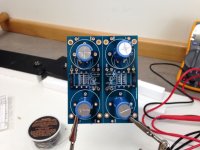
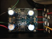
New fuse, blows right away. I'm using 500MA, 250 volt, but I'm not sure where I got that value. Is this correct? Per 6L6's recommendation, I used 4 caps, about 4700-6800uF, a pair of 4.7-10R 3W resistors and some bleeder resistors, 2.2K-10K 1W or more, MUR860 diodes in TO-220 packages. The big toroid is an 130 VA dual 22v sec Avel Lindbergh that I bought from another diyaudio member. I can look up the exact values for the caps and resistors, if that helps. Pictures are of the Peter Daniels board.
Attachments
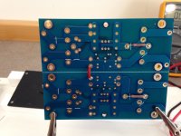
Need to see photos of it installed. To look for wiring errors.
The new fuse is a slow-blow, yes?
The new fuse is a slow-blow, yes?
Reverse the connections of the yellow and orange secondary wires. Unsolder, swap, re-solder. That will probably do it.
As for voltage, measure with the black probe of your DMM on GND, and with the red, you should have positive 32V at V+, and negative 32V at V- .
As for voltage, measure with the black probe of your DMM on GND, and with the red, you should have positive 32V at V+, and negative 32V at V- .
Reverse the connections of the yellow and orange secondary wires. Unsolder, swap, re-solder. That will probably do it.
As for voltage, measure with the black probe of your DMM on GND, and with the red, you should have positive 32V at V+, and negative 32V at V- .
Odd thing, when I used variac I got 32 volts but plugged into wall I only get 29.8 volts. Is this sufficient voltage to operate the regulators, or do I need a slightly higher voltage transformer? If you recall I used the power supply that was for some chip amp, you recommended and antek transformer. I think Budweiser used the same setup, so I assume this is ok....unless I have some other problem?
Odd thing, when I used variac I got 32 volts but plugged into wall I only get 29.8 volts.
Does your variac have a setting on the dial for more than 100%? Most do... 🙂
The regulators only need 2V or so for dropout, so even if it were as low as 26V, it would still work perfectly.
The chipamp PSU was recommended as it is 1) an off the shelf solution and 2) essentially identical to the example PSU that Wayne drew in the project article. It's still a great solution for the Pearl 2. This CRC filter and the Peter Daniel PCB will work really nicely as well.
Larry - Did you swap the orange and yellow leads?
Last edited:
Does your variac have a setting on the dial for more than 100%? Most do... 🙂
The regulators only need 2V or so for dropout, so even if it were as low as 26V, it would still work perfectly.
The chipamp PSU was recommended as it is 1) an off the shelf solution and 2) essentially identical to the example PSU that Wayne drew in the project article. It's still a great solution for the Pearl 2. This CRC filter and the Peter Daniel PCB will work really nicely as well.
Larry - Did you swap the orange and yellow leads?
Actually, my variac goes to 130, but I figured that was like the guitarist in Spinal Tap having an amp that went to 11!🙂 The chip amp power supply is very neat and compact as well. Makes things much neater than my homemade bird's nest circuits.
Russellc
Last edited:
Hi Jim, I switched the orange and yellow leads as suggested, and all is good now. 32 volts each side, direct from the wall. Now on to the RIAA boards! I used the Peter Daniels PSU board because I already had one. Thanks again.
Hi Jim, I switched the orange and yellow leads as suggested, and all is good now. 32 volts each side, direct from the wall. Now on to the RIAA boards! I used the Peter Daniels PSU board because I already had one. Thanks again.
Very nice fix. I knew secondaries were in pairs, but I did not realize that they had to be configured beyond that. The Antek I have is illustrated here:
AS-0520 - 50VA 20V Transformer - AnTek Products Corp
The secondaries are green blue /and green /blue instead of red /black and yellow/ black.
I guess on my F-5 I must have checked that out, as I used a Antek transformer. I will look at it for details. I am not at home now, but here is the board without anything on it:
http://www.diyaudio.com/forums/audio-sector/149672-universal-power-supply-pcb.html
Im assuming that as long as both blues (or greens) are in the hole closest to "A" of the A/C and both of the other color are in both holes closest to "C" I am OK? I don't see any other labeling, like "+" or "-" on the secondaries...
Russellc
Last edited:
Larry -- Great news!
The secondaries were out of phase - that's why the fuse was blowing.
The windings are marked with the lead color or side, that keeps everything flowing in the right direction.
Yep. 🙂
The secondaries were out of phase - that's why the fuse was blowing.
The windings are marked with the lead color or side, that keeps everything flowing in the right direction.
I'm assuming that as long as both blues (or greens) are in the hole closest to "A" of the A/C and both of the other color are in both holes closest to "C" I am OK?
Yep. 🙂
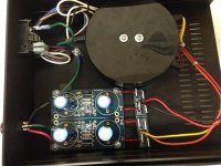
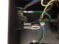
One last PSU question before I move on. I connected one of the grounds on the PSU board to my safety earth. You can see the green wire in the pictures. Is that superfluous? Likely to cause hum?
Look at the original PSU drawing, there's a bridge being used as a ground-loop breaker. It's going to hum if you don't use it.
Looking at Wayne's article, he mentions using a high current bridge rectifier; I just attached it directly to the safety earth screw. Is that okay? If I need the rectifier, which one?
In dual bridge power supplies you may conect any secondary wire in any position as you like. Phase is not important here for normal function.Take look at the diode polarity inside bridge.
BTW, Russellc,what is your final snubber capacitor position in circuit?
BTW, Russellc,what is your final snubber capacitor position in circuit?
In dual bridge power supplies you may conect any secondary wire in any position as you like. Phase is not important here for normal function.Take look at the diode polarity inside bridge.
Yes, but with a dual-secondary transformer you will make a higher than normal load on the primary and blow the fuse. 🙂
Larry, This one is fine - http://www.mouser.com/ProductDetail/Rectron/MP352/?qs=sGAEpiMZZMtQ8nqTKtFS/NgL6ac11fJu3cpGJ1SVaQM=
Last edited:
- Home
- Amplifiers
- Pass Labs
- Building a Pearl 2