Success!
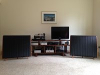
After my questions and confusions with the power supply, I was apprehensive about the finished product. But it lit up, it measured out, and it sounds fantastic. Absolutely quiet, very transparent and detailed. Plucked strings are truly luscious. A definite improvement over the expensive tube phono pre it is replacing. First album listened to: Roxy Music, Avalon. Then Suzanne Vega, Beauty & Crime; next maybe Steely Dan, Aja. This is one of those components that keeps you up for hours, pouring back through your record collection. Much thanks to Wayne and Nelson, for making their great work available to us, and to Jim for all his help. Next I think I'll do an Aleph J, but that's for next winter.
After my questions and confusions with the power supply, I was apprehensive about the finished product. But it lit up, it measured out, and it sounds fantastic. Absolutely quiet, very transparent and detailed. Plucked strings are truly luscious. A definite improvement over the expensive tube phono pre it is replacing. First album listened to: Roxy Music, Avalon. Then Suzanne Vega, Beauty & Crime; next maybe Steely Dan, Aja. This is one of those components that keeps you up for hours, pouring back through your record collection. Much thanks to Wayne and Nelson, for making their great work available to us, and to Jim for all his help. Next I think I'll do an Aleph J, but that's for next winter.
Attachments
Looks great! Well done!
Yep, it's a fantastic gift that Wayne gave us all. A simply amazing phono preamp. I know of nobody who has built it that isn't simply enchanted with it.
BTW, you'll love the amp as well...
it lit up, it measured out, and it sounds fantastic. Absolutely quiet, very transparent and detailed. Plucked strings are truly luscious. A definite improvement over the expensive tube phono pre it is replacing .... This is one of those components that keeps you up for hours, pouring back through your record collection.
Yep, it's a fantastic gift that Wayne gave us all. A simply amazing phono preamp. I know of nobody who has built it that isn't simply enchanted with it.
Start now. Listen in winter. 🙂I think I'll do an Aleph J, but that's for next winter.
BTW, you'll love the amp as well...
After my questions and confusions with the power supply, I was apprehensive about the finished product. But it lit up, it measured out, and it sounds fantastic. Absolutely quiet, very transparent and detailed. Plucked strings are truly luscious. A definite improvement over the expensive tube phono pre it is replacing. First album listened to: Roxy Music, Avalon. Then Suzanne Vega, Beauty & Crime; next maybe Steely Dan, Aja. This is one of those components that keeps you up for hours, pouring back through your record collection. Much thanks to Wayne and Nelson, for making their great work available to us, and to Jim for all his help. Next I think I'll do an Aleph J, but that's for next winter.
Congratulations! Cant wait to get mine up. Right now, I've got the BA-3 as pre burning in with .750v and DC offset 0-12 mv. Then, wire up built BA-3 power amp, THEN wire assembled Pearl 2. Then buy another 5U case for the assembled FJ. I'm trying to ignore Zen Mods Babble fish J offer, but what's a guy gonna do?
Russellc
I've been interested in the Pearl 2 for a while. I'm wondering, if I may be wasting
the circuit if I only use it with MM cartridges? (I have a modest analog
rig with a projet table and an ortofon 2m bronze MM cartridge (~5mV output) )
Thanks,
Dennis
the circuit if I only use it with MM cartridges? (I have a modest analog
rig with a projet table and an ortofon 2m bronze MM cartridge (~5mV output) )
Thanks,
Dennis
Honestly it would be a perfect match. The Pearl 2 has the ability to have more gain for MC cartridges, but it (and the Pearl) were originally intended for MM.
Build it. You'll love it.
Build it. You'll love it.
Honestly it would be a perfect match. The Pearl 2 has the ability to have more gain for MC cartridges, but it (and the Pearl) were originally intended for MM.
Build it. You'll love it.
Thanks! Need to work on the BA3 preamp first. 🙂
Cheers,
Dennis
My parts came a little earlier than I expected.🙂 The Pearl is all wired up now, except the 47.5K resistor that I had not placed yet. I think I have seen them floating around here...Also, the 4 10 ohm resistors, which I left out to power up the regulators, which should happen this evening. Will test regulator voltages. Then install the 10 ohm resistors and full power up. If all goes really well, I should have it playing tonight, we will see.
Russellc
Russellc
Thanks! Need to work on the BA3 preamp first. 🙂
Cheers,
Dennis
I recently finished my BA-3 Pre....you are going to love that one too!
Russellc
I recently finished my BA-3 Pre....you are going to love that one too!
Russellc
I'm suffering from a bit of choice paralysis. My original intention is to
build a BA3b preamp, as I have all the parts (minus the attenuator)
and my amp and digital source support balanced connections.
However, I will need to use single-ended input for phono and this
post is giving me some pause:
http://www.diyaudio.com/forums/pass-labs/201281-burning-amp-ba-3b-balanced-46.html#post4312876
So I'm musing whether I should just build (and be happy) with the
single ended BA3 preamp...
Dennis
I went through the same wonderings....I'm sure there are those that disagree, but I am fine happy with the single ended, and as you point out, and I believe I heard Nelson say it (?) there is no balanced cartridge......maybe there is, (I will try to find the thread.) I dont know and I doubt I will buy it if there is!
You can always build single ended and rebuild the project balanced...I now ordered an extra BA-3 board...do the same and acquire the parts to have on hand for peace of mind. Shoot, I even have the F-4 boards and parts if I want to do the whole thing. For that matter, I have a Pumpkin Shunty Kit if I really want to go nuts. They are all sitting in the drawer while I listen single ended.
Bounce it off Buzzborb, he leans heavy to the balanced side with things BA-3.
Russellc
Last edited:
Fire up not so good...
I fired up my Pearl 2 without the 10 ohm resistors, so I could check proper operation of regulators without operation of the rest of the circuit. I had about 28,44 volts DC before the regulators. With one multimeter lead on the ground pad on the board, the left side showed a little over 26 volts after the regulator on both test points. Moving to the other side, one regulator test point showed the same as the other 2, but the third just showed a few mv.
Going back to check the others, one by one they all went to just a few mv. I guess the regulators are dead? I have a few extras, but without some idea of why they cooked, I dont want to replace them, just to see them cook.
Ideas? Wait a minute, looking at the schematic, without the 10 ohm resistors, do the regulators get any juice? looks like without R1 and R2 nothing goes to the regulator, while R3 and R4 would prevent the rest of the circuit from getting energized, no? On the other side, it looks like R30 and R32 are required to get voltage to the regulators, while R31 and R33 would keep the voltage from getting to the rest of the circuit.
Do I need to install R30 and R32, R1 and R2 in order to test the regulators? If so what was I measuring?
Maybe, and its a big maybe, I didnt fry anything?
Russellc
Last edited:
Think I answered my own question. I left out the wrong 10R resistors, and installed the ones I shouldnt have! Fortunately, I bought a lot of each value. Looks like I need to remove R3, R4, R31 and R33, and install R30, R32, R1 and R2. (in order to test regulators without energizing the rest of the circuit)
Have no idea what I was measuring, maybe it was tiny mv voltage off the caps? I dont know
Good grief,
Russellc
Have no idea what I was measuring, maybe it was tiny mv voltage off the caps? I dont know
Good grief,
Russellc
Yup, that did it. 24.4 at each regulator test point. Now to hook up the OTHER 10R resistors and see what happens!
Russellc
Russellc
All fired up, 1.63 and 1.67 across R6. Zero volt adjusted by P1 drifts around a little, 0 to a few mV. Outputs measure 0 to 7 mV. R6 to ground is 20.6 and 20.7. Letting it cook a little while.
comments on measurements? Is it ready to try? Dont want to blow up F-5, better drag out the bullet proof JBL power amp for testing.
Russells
comments on measurements? Is it ready to try? Dont want to blow up F-5, better drag out the bullet proof JBL power amp for testing.
Russells
Last edited:
Pass DIY Addict
Joined 2000
Paid Member
I'm starting to populate my Pearl boards and am having trouble finding a ZVP331 from Zetex as indicated on the parts list.
Will this one do as a substitute:
ZVP3310A Diodes Incorporated | ZVP3310A-ND | DigiKey
Thanks,
Eric
Will this one do as a substitute:
ZVP3310A Diodes Incorporated | ZVP3310A-ND | DigiKey
Thanks,
Eric
Apparently Zetex was acquired by Diodes a few years ago so I would assume it's still the same part.
Dennis
Dennis
Great news!!! Congratulations on your project making music!
Hiss -
Did you verify that all the voltages are correct as compared to the schematic with the voltage notation? (Place the black lead of your DMM on power ground and probe around with the red lead set to DC volts.)
Did you adjust the pot to get zero volts at the test pad? Is that point stable?
Do you have any output offset?
Is C7 installed?
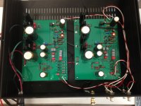
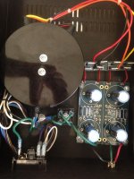
Please post well-lit, in-focus photos so we can take a look at it.
Lastly, do you have any hummm on the outputs?
I cant get 0 volts at test pad, not for very long, seems to run up and down a bit...If I adjust P1 to get the 21 volts at the other test point, I have 7 or 8 volts at test point that should be zero. Adjusting P1 to attempt 0 volts, or as close as I can get, I have about 22 volts where 21 is desired. Across R6 I am getting 1.6 volts on both sides. I do have some DC offset at the outputs, it moves around from 0 to a few mV, once in a while as high 10mV or so.
C7 is not installed. Have not tried it for sound yet. Is the mosfet cooked? Seems like you said if there was any voltage at the test point the mosfet is likely toast. Seems odd its like that on both sides. What if any is acceptable in terms of DC offset?
Russellc
Last edited:
Photos to come. Ive taken them just need to get them on the computer.
So... I started checking the voltages for the left channel as per the diagram and recording them. Funny thing though. When i was done, that channel no longer is playing music or hissing.. Just a very very low output in the tweeter...! this hiss is rather Annoying when the record isn't playing.
With all other stereo equipment off here are the readings:
Pearl voltages (over one minute)
Left
+dc pad: 30.87 to 30.98
-dc pad: -32.15 to -32.29
+ Rail at R4: 24.02 to 24.03
- rail at R10: -23.65 unvaried
P1: +25mv to - 23mv fluctuating/drifting up and down. One sample saw fluctuations of +- 300mv
R6 1.606v
R9 20.05v
C15 (- side) 0 volts. (+side) -39mv to +35mv
Input: 0 mv and 0 mv
Output: sample one: -8.8 to +11mv 0mv at ground
Sample two: -20 to +13.9mv
( polar elna silmic)
Strangely, when the other equipment is on, the voltage at p1 fluctuates much much wilder... Around 1volt. Last night when i first powered it up p1 only fluctuated a couple of mvs and -may- have demonstrated less hiss than today.
Grrr! What might have happened to my left channel? I tried testing the output with a test record tone at 1khz with a multimeter set to Hz.. Which did nothing.. Produced zero. Did i make an oops?
Very similar readings to mine...
Russellc
Pass DIY Addict
Joined 2000
Paid Member
Apparently Zetex was acquired by Diodes a few years ago so I would assume it's still the same part.
Dennis
Thanks, Dennis! My penalty for not jumping on *EVERY* project AS IT COMES OUT 😀 😱
I cant get 0 volts at test pad, not for very long, seems to run up and down a bit...If I adjust P1 to get the 21 volts at the other test point, I have 7 or 8 volts at test point that should be zero.
What test point is that?
Adjusting P1 to attempt 0 volts, or as close as I can get, I have about 22 volts where 21 is desired.
That's pretty close...
Again, close.Across R6 I am getting 1.6 volts on both sides.
on the output pads themselves? Or before the cap. I.E., R17?I do have some DC offset at the outputs, it moves around from 0 to a few mV, once in a while as high 10mV or so.
It has nothing to do with sound. It's for ultrasonic oscillation, and is usually left outC7 is not installed. Have not tried it for sound yet.
That's a decent assumptionIs the mosfet cooked? Seems like you said if there was any voltage at the test point the mosfet is likely toast.
There shouldn't be any downstream of the cap.What if any is acceptable in terms of DC offset?
- Home
- Amplifiers
- Pass Labs
- Building a Pearl 2