
I’m late to reply, but is this still available given the focus upon the Pearl 3?I just made an updated Pearl power supply for the PassDIY Pearl Phono. The design goals for the board and power supply included:
It's now running on my Pearl 2, and I'll be shipping it in a few days for a long term beta tester.
- Compact with PCB mount transformer
- Able to fit in an off-the-shelf chassis (e.g. Hammond) OR into the 10x10 grid of a Modushop / DIYAudio chassis
- CRCRC filtering for each rail
- Include optional snubber circuitry
- Include ground break rectifier on the PCB
- Include A/C cap on the PCB
- Flexibility for 120/240 mains
- LEDs on PCB (for rail voltage indication and front panel indicator)
Rails are ~34V, with one a little higher than the other. I used the PCB fab house to make aluminum PCBs as front and back plates.
I plan to write up a Build Doc and BOM, then offer up the main PCB and front/back plate PCBs. Stay tuned. I have a few sets on hand, PM if interested.
I purchased a Pearl 2 set of boards with FETs last year--unopened. I have all the parts for the boards from Mouser (unopened) per the Mouser BOM for this project. I am willing to sell for $250 if anyone is interested. I've been through treatment for cancer and don't have the ability to focus on it right now.
Very to sorry to hear that! I was just about to order boards and parts and saw your message. I’ll buy them from you.
PM sent.
PM sent.
Dneu2011 ... Thank you! Let's connect via email and we can exchange info. And Moderator. Thanks for the push. 🙂
… …
… …
Last edited by a moderator:
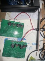
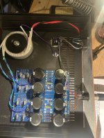
Hello, I have strange problem with my pearl 2 regulators/Power supply. I built my power supply and the voltages looked good (~+/- 30V). I then stuffed the regulators section of the pearl boards and the voltages were way off (~+8V & ~-3.5V on both boards). I then checked the voltages coming out of the power supply and they were also ~+8V & ~-3.5V. After that, I disconnected the umbilical cord to the pearl boards and the voltages of the PSU started rising again to a steady ~+/- 30V. I had also purchased a 2nd set of pearl 2 boards from pass DIY so I stuffed those boards as well and got the same results as the first set of boards. Thank you for you help and let me know if any other info is needed.
Attachments
The first guess is the cable (or the jacks) isn't wired properly. Check the pin numbers and make sure you have consistency across all 4 connections. (The two plugs and the two jacks.)
That the PSU comes back to expected voltage when unhooked from Pearl boards is a good sign.
Also, make sure you have the 7824s and 7924s in the proper positions.
That the PSU comes back to expected voltage when unhooked from Pearl boards is a good sign.
Also, make sure you have the 7824s and 7924s in the proper positions.
Thanks for the fast responses guys.
The brown jumper jumps pin 1 to pin 4...Pin 4 is the ground conductor and I attached the umbilical cord's shielding to Pin 1. The shielding isn't connected to anything at the other end. I wasn't sure if this would make a difference, but I thought that it couldn't hurt.
I'm fairly certain that the umbilical cable wire is consistent throughout. The way that I checked this was by turning the power off and doing a continuity test with an ohm-meter from the pads on the power supply board to the pads on the pearl 2.
Unsolder both pearl boards.
Meter to DC volts, 200 if manual range.
Put black probe on your blue ground wire that would attach to the pearl boards.
With red probe, you should read about +30VDC on the red wire, -30VDC on the black wire. Verify this is true for both wire sets.
After that, verify that the regulators are in the proper positions on both boards.
Thanks Ben Mah, I think that you found the problem. I had 10K for R2 and R7 (the R's in the CRC) rather than 10 ohms. I have 2.2K for R9 and R10 (the bleed resistors). I will order some 10 ohm 3W resistors to replace these. Thank you 6L6 and mheschel as well for the advice.
- Home
- Amplifiers
- Pass Labs
- Building a Pearl 2