Thank you very much for all the suggestions.
@Monk55 Jakelectronics dot com ask 50$ for shipment, quite hight for just couple $ of value
so far I can find ZTX450STZ from Farnell (thanks @Pars) and ZVP3310 but is SMT
@jackinnj I don't have the background to choose which one to buy based on simulation or data sheet info.
is the ZTX450STZ the equivalent for ZTX450 or better to go with 2N4401 you have simulate?
and, better ZVP3310 SMT or TP2104N ?
I assumed that the ZTX450STZ is the same as the ZTX450? On Digikey, the plain ZTX450 datasheet is pulled up. I also noted there are STOA, etc. variants as well.
Hello mvaldes,
alweit has ZETEX ZVP3310. I have bought several times from him - very good! Not matched!
https://www.ebay.de/itm/230962104294
Cheers
Dirk 😉
alweit has ZETEX ZVP3310. I have bought several times from him - very good! Not matched!
https://www.ebay.de/itm/230962104294
Cheers
Dirk 😉

I forgot: be very careful touching them - the ZVP3310 are very static sensitive devices.
Cheers
Dirk
Cheers
Dirk
Just finished my Pearl II. Very enjoyable to build! I wanted easily adjustable gain so I mounted resistors and DIP-switches vertically to make everything fit. The power supply and the amplifier board are mounted in matching Galaxy chassis. Listened to some records today and everything works as expected and it truly sounds great! I've been using a EAR 834 clone recently, which I have been very pleased with, but this is something else. I might be confirmation bias of course, but still ...


I found some old Zetex document which indicates that STZ is the code for packaging in ammo pack of 1500:I assumed that the ZTX450STZ is the same as the ZTX450?
Thanks to all for the valuable information. I finally ordered some ZTX450's from Farnell (thanks @Pars) and the ZVP3310 from the ebay seller listed by @cubicincher.
All the other components I'll buy from Mouser.
PCB's are also on their way to my home...🙂
All the other components I'll buy from Mouser.
PCB's are also on their way to my home...🙂
Boards and JFET's in hand from Pass DIY. I had trouble finding negative voltage regulators, MOSFETs and NPN transistors in stock; had to resort to ebay for those. All other components headed my way from Mouser. Amazing how availability changes from week to week!
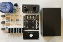
I just made an updated Pearl power supply for the PassDIY Pearl Phono. The design goals for the board and power supply included:
Rails are ~34V, with one a little higher than the other. I used the PCB fab house to make aluminum PCBs as front and back plates.
I plan to write up a Build Doc and BOM, then offer up the main PCB and front/back plate PCBs. Stay tuned. I have a few sets on hand, PM if interested.
- Compact with PCB mount transformer
- Able to fit in an off-the-shelf chassis (e.g. Hammond) OR into the 10x10 grid of a Modushop / DIYAudio chassis
- CRCRC filtering for each rail
- Include optional snubber circuitry
- Include ground break rectifier on the PCB
- Include A/C cap on the PCB
- Flexibility for 120/240 mains
- LEDs on PCB (for rail voltage indication and front panel indicator)
Rails are ~34V, with one a little higher than the other. I used the PCB fab house to make aluminum PCBs as front and back plates.
I plan to write up a Build Doc and BOM, then offer up the main PCB and front/back plate PCBs. Stay tuned. I have a few sets on hand, PM if interested.
Attachments

Last edited:
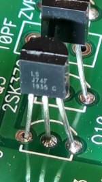
Same thing has happened to me. I ordered boards and JFETs from PassDIY a few weeks ago. After powering the boards up today I see over 24V at the test pad and adjustment of P1 makes no changes. Upon closer inspection I find I also was supplied with incorrect J74 JFETs.You will not believe this. Wild voltages at P1 test pads (cont.)
...
Gents, you will not believe this. I researched the entire web to see who else had my same problem, wild high voltages at P1 test pad -23.5 Volts (which should theoretically be close to 0 volt). Guess what, a few years back, there was a post on this very forum, stating a very similar symptom of wild voltages at various test points which made no sense whatsoever. The original poster got a tip from some diyAudio guru (maybe one of you guys), pointing out that the transistors could be the culprit. He looked at his matched JFETs which he got from PassDIY. His JFETs were J74 bl9c, which I also received and installed. These JFETs were not comparable to or interchangeable with 2SK370. I don't think they are even close.
...
Attachments
Hello DamonB,
there seems something wrong. 2SK370 are N-channel-JFets. You've got Linear Systems LSJ74 P-channel-JFets.
Write an E-mail to PassDIY.
Cheers
Dirk
there seems something wrong. 2SK370 are N-channel-JFets. You've got Linear Systems LSJ74 P-channel-JFets.
Write an E-mail to PassDIY.
Cheers
Dirk
Same here. Just got the pcb and Jfets from PassDIY and Jfets are labeled as LS J74. I've not powered on yet...Same thing has happened to me. I ordered boards and JFETs from PassDIY a few weeks ago. After powering the boards up today I see over 24V at the test pad and adjustment of P1 makes no changes. Upon closer inspection I find I also was supplied with incorrect J74 JFETs.
I called PassDIY and they put replacements in the mail on the same day. I should have them in hand sometime this week.Hello DamonB,
there seems something wrong. 2SK370 are N-channel-JFets. You've got Linear Systems LSJ74 P-channel-JFets.
Write an E-mail to PassDIY.
Cheers
Dirk
I've sent email to PassDIY contact and today they sent me a replacement.
Now I've about 10 days to desolder the wrong ones w/o damaging the board🙂
Now I've about 10 days to desolder the wrong ones w/o damaging the board🙂
PassDIY got the correct JFETs to me right away and I swapped them into the boards. Offset was then easily adjusted down to 0 mv and all immediately worked as it should. I've not owned a turntable until recently when I restored a Technics SL-B2 with a Shure M97 cartridge. This originally drove my preamp through a $25 Pyle phono preamp from Amazon. The Pearl 2 of course makes the Pyle sound embarrassingly bad! Far more dynamic everywhere and dead silent. The old phono preamp sounded veiled, stale and closed in with no deep bass and flat highs while Pearl 2 makes recordings from the turntable have LIFE along with the bass and airy highs I expect from my system. I selected Pearl 2 purely on the experience I had building Nelson's Firstwatt F6 amps and I'm very pleased with my choice!
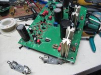
On a side note I did not kill either of the Q2 MOSFETs during assembly. Heeding the warnings from others here as to their static issues I was careful to not touch the legs with my fingers nor metal tools, carefully spreading the legs with a wood toothpick for soldering into the boards. Each leg was then carefully soldered while ensuring the iron touched only one leg at a time. When trimming the leads off the bottom of the board I was also careful to ensure only one leg was touched at a time. Either this did the trick, or I was lucky.
Below is how I implemented the R14 and cap/bypass cap update to prevent oscillation as this was the tidiest layout I could come up with.


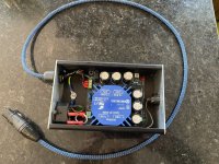
Power supply board from audiosector.com allowed the compact build I desired.

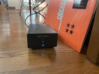
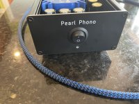
Complete power supply inside a repurposed DAC enclosure.

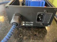
For safety the extra holes on back of this repurposed enclosure were covered with blanking plates bolted from inside. I used MEK to remove the previously silk screened labels without damaging the powder coating. The umbilical I used has a very thick rubber jacket and 8 individually PVC insulated solid copper conductors inside. Overkill for this application but was in the parts box. It was a complete PIA to solder this stiff cable to the jacks and attaching the XLR plug had me rethinking my choice as far too much time and effort was consumed.

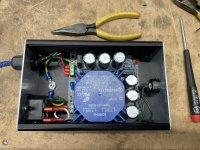
Pearl 2 inside a 2U case. Power inlet at far left of rear panel, then RCA inputs and and ground post, then RCA outputs. Shielded 75 ohm mini coax cable for input and output wiring. 4 pin XLR type cable from power supply to Pearl 2 boards. I used this plug hoping it will prevent anyone from accidently trying to insert a standard 3 pin XLR preamp cable. Ground post on rear panel is isolated from chassis; this post and both boards attach to the star chassis ground through a bolt and star washers. RCA input and output jacks also isolated from chassis per build instructions.


Rose gold cabinet handles from Amazon bolted onto front of 2U enclosure so it matches the appearance of the Firstwatt power amps in my home. Single blue LED on power supply (of course!) MEK was used on front panel of repurposed power supply enclosure to remove manufacturer's labels. "Power" label above switch was left alone.

Pearl 2 boards' pilot LED visible through chassis vents. I figured running these LED to the front panel would be gratuitous and overkill so instead I stood these LED high off the boards to make them easy to view through the vents.


Thank you to everyone who has contributed to this thread. Maybe I'm a vinyl greenhorn but I cannot imagine anyone being unhappy with a Pearl 2!
On a side note I did not kill either of the Q2 MOSFETs during assembly. Heeding the warnings from others here as to their static issues I was careful to not touch the legs with my fingers nor metal tools, carefully spreading the legs with a wood toothpick for soldering into the boards. Each leg was then carefully soldered while ensuring the iron touched only one leg at a time. When trimming the leads off the bottom of the board I was also careful to ensure only one leg was touched at a time. Either this did the trick, or I was lucky.
Below is how I implemented the R14 and cap/bypass cap update to prevent oscillation as this was the tidiest layout I could come up with.
Power supply board from audiosector.com allowed the compact build I desired.
Complete power supply inside a repurposed DAC enclosure.
For safety the extra holes on back of this repurposed enclosure were covered with blanking plates bolted from inside. I used MEK to remove the previously silk screened labels without damaging the powder coating. The umbilical I used has a very thick rubber jacket and 8 individually PVC insulated solid copper conductors inside. Overkill for this application but was in the parts box. It was a complete PIA to solder this stiff cable to the jacks and attaching the XLR plug had me rethinking my choice as far too much time and effort was consumed.
Pearl 2 inside a 2U case. Power inlet at far left of rear panel, then RCA inputs and and ground post, then RCA outputs. Shielded 75 ohm mini coax cable for input and output wiring. 4 pin XLR type cable from power supply to Pearl 2 boards. I used this plug hoping it will prevent anyone from accidently trying to insert a standard 3 pin XLR preamp cable. Ground post on rear panel is isolated from chassis; this post and both boards attach to the star chassis ground through a bolt and star washers. RCA input and output jacks also isolated from chassis per build instructions.
Rose gold cabinet handles from Amazon bolted onto front of 2U enclosure so it matches the appearance of the Firstwatt power amps in my home. Single blue LED on power supply (of course!) MEK was used on front panel of repurposed power supply enclosure to remove manufacturer's labels. "Power" label above switch was left alone.
Pearl 2 boards' pilot LED visible through chassis vents. I figured running these LED to the front panel would be gratuitous and overkill so instead I stood these LED high off the boards to make them easy to view through the vents.
Thank you to everyone who has contributed to this thread. Maybe I'm a vinyl greenhorn but I cannot imagine anyone being unhappy with a Pearl 2!
After recently moving house, I've been emptying out cardboard boxes full of goodies and came across the Pearl 2 that I almost finished over 2 years ago, and in the process of getting it up and running I think I may need to replace a couple of items. Don't ask, it's a very boring and even more embarrassing story. Long story short I'm trying to figure out which JFETs to get. The original kit came with matched 2SK370s but I believe I should be able to use matched LSK170s. My question is, which ones from the store; 6-8mA or 8-11mA? I checked Waynes original article and scoured this post to see if I could find the answer but seem to come up short.
Thanks in advance,
Gary
PS. I'm assuming it's only Q6 to Q9 that need to be matched????
Thanks in advance,
Gary
PS. I'm assuming it's only Q6 to Q9 that need to be matched????
Last edited:
- Home
- Amplifiers
- Pass Labs
- Building a Pearl 2