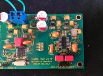
I've not yet started the build, i'm located in France, Plaisir (Yvelines) if someone is near me and wants to share or build it together i would be pleased. Continue in PM 🙂JP - the sound of V3 is truly addictive once dialed in. Changing C17 to ceramic made everything snap into place and I've been listening to it more or less non-stop since making that change. It's got great tonality and even the bass seems to have improved with better texture and definition. Surprisingly good for such an inexpensive DAC. This is some of the better digital sound I've had in my system.
Having a 2nd DAC really helps sorting out which changes are real improvements over just different. Perhaps we should share our locations so that people who are close to one another can bootstrap one another up the learning curve. For anyone in the SF Bay area, I'm glad to let you compare your build to what I've done. I'll be away for the holidays for the next week or so but back after that.
Happy holidays everyone.
---Gary
Well, I have here thought that if I cannot get home to build something, it is maybe better to bring the project and tools with me... So let's see after tomorrow how this project would go on.
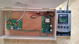
I just finished the dac and hook up to the CDP at the moment because I don't have a USB to SPDIF converter yet. The pads for the Q2 were tight and the WM8804 needed to be patience, dial in the correct soldering temperature and good quality of wick to remove excessive solder on the WM8804. Thank you JP and SB to make this GB happen.
By the way, anyone can recommend a decent USB to SPDIF converter?
Sidney
Hi Sidney, beautiful build ! An example for a good layout with 230 V AC far away from SPDIF and L+ R outputs. IMO you build can inspire many builders for a successful placement of boards and connections. One tiny point is that the power LED has little function where it is now 😉 How does it sound ?
I take many like to have all connections at the backside of the case. In that case please route the 230 V AC wiring far away from the main DAC board and keep AC wiring short.
I see our choice for changing the MKDSN for Molex KK connectors has resulted in people soldering input and output wiring straight to the board. Pity as they are good connectors but one needs to have the crimping tool. It would have been a success if we had delivered cable harnesses with the board I guess. Again something that is learnt in the process...
Last edited:
Another DAC is singing right now!
This is my first DIY dac and: it has been difficult but satisfying 😀
It didn't work the first time, so I was worried for Q2 🙁 After, I checked the voltage on ES9023 and WM8804 (thanks atapi!) and everything matched within 5%
Finally, it was a dry joint on wm8804 pin 2 (the sw mode pin, if I'm not wrong)! After that, it started to play 🙂
Thanks to JP, Subbu for the design & GB. Thanks to Phil for the parts GB.
An externally hosted image should be here but it was not working when we last tested it.
You struggled but you are still on your feet and succeeded. How does it sound ?
By the way, anyone can recommend a decent USB to SPDIF converter?
WaveIO from Luckit (also visually a piece of art...)
Hiface EVO (which is what I am using now - before I have my WaveIO-Subbu DAC combo finished) Use a very good power supply for that one (actually for all digital gear) - or a battery supply.
You struggled but you are still on your feet and succeeded. How does it sound ?
I say that this is a big step forward for my audio setup 😀
On the other hand, I have several steps before I can make a well collocated judgment:
1) put everything in a nice metallic case,
2) upgrade my sources (HDX900 mediaplayer and a cheap pioneer dvd player) with nice 75Ohm BNC SPDIF connections,
3) upgrade C17 to a ceramic one (I understand it's another big improvement),
4) make a good DIY coax cable
5) maybe (maybe), make a spdif switch to accomodate 2-3 sources...
hi everyone
got the dac working just fine for the past few days now, today i inadvertently touched the ground and positive spdif together and now i can only see the power supply supplying a very dim light when it is turned on. i really don't know where to check where that short is coming from, it's on the dac that's for sure but where, any help would be appreciated, thank you.
reo
Ps: many thanks to the people that have made this project in to reality.
yes it does, i checked it just to make sure.
as soon as i connect it to the dac it shorts to a very dim light.
regards
as soon as i connect it to the dac it shorts to a very dim light.
regards
The gurus might better advise you, but I'd check l3, 4, 5 & 6 first to see if all is OK to that point. The read sheet in the first post may be helpful. If you look at the schematic from the "l"s back to power in you can see the power path if needed.
Last edited:
Hello, I would check:
- U3 & U4 pins continuity (with no PS): from the photos... it seems that a short could be there.
- RN1, third resistor from top: it seems that the right pin is not well soldered.
- of course, I do not think that an occasional short on the input spdif made a problem to the DAC. It was just the event that triggered a already present problem...
go figure, started working again like nothing ever happened, surely there is someone on the board not cooperating, also might have filled up a component with negative charge or something but will check for bad solder that might just be the case for this stop and go.... thanks guys much appreciate your output.
regards
reo
regards
reo

Last edited:
yea thanks, been working with loupes all my life as a master engraver but seems when you think that you overseen everything......
again thank you for your output.
regards
reo.
PS for those who are looking for converters this company's site.... SHEN ZHEN QLS ELECTRONIC TECHNOLOGY CO.,LTD. (HIFI Audio sector) has some options.
again thank you for your output.
regards
reo.
PS for those who are looking for converters this company's site.... SHEN ZHEN QLS ELECTRONIC TECHNOLOGY CO.,LTD. (HIFI Audio sector) has some options.
...all my life as a master engraver....
Hmmmm - Do you do the type that can be used on project front panels?🙄
did mostly engravings in 3D by or from from stencils but will not venture on panels., a pantographs is best suited for that type of work. Jewellery stores usually have the fonts and personnel to deal with those circomstances.
regards
reo
regards
reo
- Home
- Source & Line
- Digital Line Level
- Build thread - building the Subbu DAC V3 SE