Hi Bob,
I have several DIY amps including a F5, AlephJ, SKA, and never had any hum issues. I ground the amp PSU to the IEC ground through two reversed diodes and a 10R resistor in parralel. The amp boards are grounded to the PSU boards. I'm still waiting on parts to get around to my V3 build.
PJN
I have several DIY amps including a F5, AlephJ, SKA, and never had any hum issues. I ground the amp PSU to the IEC ground through two reversed diodes and a 10R resistor in parralel. The amp boards are grounded to the PSU boards. I'm still waiting on parts to get around to my V3 build.
PJN
Thanks PJN. I posted on one of the Pass threads this morning and got some interesting answers. I'll give them all a try.
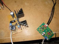
One more finished. My first SMD project and managed not to burn anything!
Of course soldering not so nice as others here, but it works.
Initially I thought I made a mistake or burned something, as I had the right voltages but no sound, but I only had to reflow some joints on Q2 and Q1.
Info here helped a lot.
Power supply regulator is a Salas reflector.
Sounding really nice right now!
Attachments
If anyone is interested, there was a problem with the grounding of the Pass BA-3 amp. Fortunately another member had sorted it out and gave direction. A seperate problem totally unrelated to the V3 did develop but was also resolved.
You can read about it starting here and follow through to today's post if you think a V3-Pass combo is in your plans.
You can read about it starting here and follow through to today's post if you think a V3-Pass combo is in your plans.
Correct. The other major change was putting all the grounds on the same star ground/bus. That was close to what I had but the two channels were done seperately (individual stars) without a unique connection back to earth. Still have the one MyRef to get hum free, and I suspect that will also center around a CL-60.
Just a note - Subbu/JP DAC sounding simply excellent with the definitively clean Pass amp. Working well together for about 3 hours. The lower mids are tight with the bottom being deep and well damped. There could be a little more top end shimmer, but I'm looking forward to the upcoming V3 cap upgrades to dial that in. But the stock build sounds really, really good to these ears. 🙂
On the subject of grounding, what is recommended for the DAC? Just connect the mains ground to the chassis?
I'm not recommending this for anyone on a safety basis - but I installed a two wire set on the current platform. I will most likely do the same for the final chassis that will essentially be double insulated - some use of wood/Plexiglas.
(As shown still needs heat shrink at receptacle.)
(As shown still needs heat shrink at receptacle.)
Attachments


the suggested parts for C17 is now 1uf ceramic. Is there any ill effect if I put a 2uf for C17, I happen to have some lying around.
C21 suggested with 470uf polymer, would it be also good - sound wise - to put tantalum there in same value ?
C21 suggested with 470uf polymer, would it be also good - sound wise - to put tantalum there in same value ?
I think 2uf is also fine for c17. Regarding C21 i think the choice is a matter of taste. JP recommended Vishay, some others found polymer sounding better, my choice was a 220uf BG PK. You are free to find your caps to your taste.
atupi,
the // oscon SEPC or polymer Nichicon FA (the red on top) with a BG NX (the red one) give me outstanding result in another DAC
the // oscon SEPC or polymer Nichicon FA (the red on top) with a BG NX (the red one) give me outstanding result in another DAC
I think 2uf is also fine for c17. Regarding C21 i think the choice is a matter of taste. JP recommended Vishay, some others found polymer sounding better, my choice was a 220uf BG PK. You are free to find your caps to your taste.
Ha ! I got 2 pieces BG PK 220/4 from an audio friend. Must try them.
atupi,
the // oscon SEPC or polymer Nichicon FA (the red on top) with a BG NX (the red one) give me outstanding result in another DAC
Agree - best sound quality comes from red capacitors 😀.
---Gary
the Santa capacitor, like the red Baron, red pcb, red cars: it sounds better.
2 red caps are even better, it's the R2R sound !
2 red caps are even better, it's the R2R sound !
Last edited:
Ha ! I got 2 pieces BG PK 220/4 from an audio friend. Must try them.
Waiting for your feedback JP!
One more finished. My first SMD project and managed not to burn anything!
What was your gun and technique Mr George?
What was your gun and technique Mr George?
I used an OKI PS-900 and 1,8mm chisel tip.
Difficult to solder was the regulators an Q2, were I had to use a JBC 15Watt with a very fine tip, in order to flow the solder. One solder point the time, while blowing and then wait the chip to cool down, in order to continue.
I also used a flux pen.
Magnifying glass of course and check every soldering point.
- Home
- Source & Line
- Digital Line Level
- Build thread - building the Subbu DAC V3 SE