Is your bias still 2.5A after 1h ?
How about your Dell smps, it’s not overheating?
Short the INPUT and add a 8ohm load.
How about your Dell smps, it’s not overheating?
Short the INPUT and add a 8ohm load.
Pass DIY Addict
Joined 2000
Paid Member
Yep - bias holds pretty steady at 2.5A once things are warmed up. The power brick is rated to deliver 12.3A at 19.5v (total of 240w) and is mildly warm after an hour.
No inputs or outputs are connected. Is this causing it to oscillating it's way into oblivion? I've burned two transistors now...
No inputs or outputs are connected. Is this causing it to oscillating it's way into oblivion? I've burned two transistors now...
Pass DIY Addict
Joined 2000
Paid Member
No, I didn't install the 20v zener. I have them, but the BoM indicates they are optional and it's not shown in the schematic in Figure 1. Since I didn't find a description of it in the article, I left it out. Mike's image at the start of the thread shows the zener is missing as well.
I don't understand what role the zener serves...
I don't understand what role the zener serves...
The 20v Zener ensures that the max Vgs of the Mosfet (20v)is never above its limit.
See here:
what's the purpose of the zener, mosfet | All About Circuits
See here:
what's the purpose of the zener, mosfet | All About Circuits
Pass DIY Addict
Joined 2000
Paid Member
I have a single IRFP250 left. I'll install the zener and test with my 8R dummy load and see what happens... I still don't understand how voltage can rise above 20v with a 19.5v PSU and no signal present.
I'll pick it up again tomorrow night and see how things go.
I'll pick it up again tomorrow night and see how things go.
Hopefully by tomorrow someone will come with an explanation
I would test with the input shorted.
I would test with the input shorted.
....don't understand how voltage can rise above 20v with a 19.5v PSU and no signal.....
You have AMPS flowing in an inductor the size of a melon.
If current is cut-off, the inductor KICKS, "trying to keep Amps flowing".
Ideal inductor, instant cut-off, voltage kicks to infinity.
Iron-core inductor won't kick to infinity, but 10:1 kick is commonly seen in "working" systems (car spark coil), and some higher if NO load.
Here's a sim. The values are wrong but the trend is clear. If current is broken quickly, inductor kicks to -600V. If Gate has a cap, most of this appears across the Gate-Source oxide, which is rated 20V and dies easy at 30V-50V.
It is situational. If current is not cut-off but fades-away, the kick may be tiny. If choke is loaded to about 19V/2.5A (8r) the kick is <19V.
The Zener is not really optional.
Many MOSFETs have an internal Zener. This may be a very small diffusion not able to absorb the energy in a melon-choke. Get a BIG junction, 1W or more.
No-load is worst-case. Have a load. 10r 10W is good for the bench.
Don't yank the DC connector. If you yank the wall-plug of the Dell-wart, it *may* come-down slowly on stored charge.
Attachments


Put >100uFd on the rails ON the card. If DC power is yanked, this gives a slow let-down and greatly reduces the kick.
(Side-note: you'd think you'd want a rail bypass "in the design". As implemented, audio current goes all the way out to the Dell-wart and back to complete the path.)
(Side-note: you'd think you'd want a rail bypass "in the design". As implemented, audio current goes all the way out to the Dell-wart and back to complete the path.)
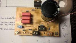
As far as I can see from the PCB the zener is placed behind the R2 (gate stopper) to the Source. Is it better to mount the zener directly from G to S on the mosfet?
So far I have not mounted it at all but I have mounted the PCB on the heatsink but should be able to mount the zener and solder it from the front side....there seems to be "through the hole connection" even that it is a single sided PCB.
My choke has only about 0.1 Ohm DCR so max. 0.3V over it. So even a x100 kick may not destroy the mosfet…...in my case.
I have a single IRFP250 left. I'll install the zener and test with my 8R dummy load and see what happens... I still don't understand how voltage can rise above 20v with a 19.5v PSU and no signal present.
I'll pick it up again tomorrow night and see how things go.
Hi Eric,
I have a setup similar to yours - MOT as a load (207mH, 1.9ohm RDC), 20V supply voltage, IRFP150 fet (from RS Comp.), everything assembled on a stripboard, instead of a PCB and NO ZENER between gate and source.
Bias current is 1.6A. Have not tried higher bias, but might give it a chance, my heatsinks are massive, barely warm at this current.
Everything runs fine, has been for a few weeks now.
So, either try to lower the bias (easy) or replace the fets with something from a trusty source.
With such a simple circuit there aren't many things that can go wrong.
Also check and re-check your solder joints, the culprit might be there.
Attachments
-
 WP_20180528_18_41_53_Pro.jpg750.4 KB · Views: 678
 -
 WP_20180530_19_30_33_Pro.jpg725.5 KB · Views: 687
 -
 WP_20180528_18_41_29_Pro.jpg677.6 KB · Views: 614
 -
 WP_20180530_19_30_44_Pro.jpg638.2 KB · Views: 617
 -
 WP_20180530_19_31_14_Pro.jpg581.7 KB · Views: 603
 -
 WP_20180528_18_40_42_Pro.jpg652.7 KB · Views: 279
If you're having an issue then I'd install the zener, connect a load, and try lower bias first, then move up and see what you get. 🙂
I'm also curious, when you power off are you pulling the plug from the wall or pulling the barrel connector out?
I'm also curious, when you power off are you pulling the plug from the wall or pulling the barrel connector out?
Pass DIY Addict
Joined 2000
Paid Member
I'm starting to see things more clearly now, thank you for all of the input!
The amp worked properly for over an hour - the bias current creeps up as the mosfet and sink heat up, so I kept adjusting it down to maintain my target bias setting. The choke warms up a little during this time - definitely below body temp, but warmer than ambient. After the hour mark, I just pulled the DC plug at the board to power down. Not understanding the function of the zener and choke, this is apparently where things died. That's one hell of a spike as the field in the inductor collapses! No wonder the mosfet failed...
I did check and double check my soldering - no errant bridges and no cold joints. I pulled one leg on each of the resistors (easiest part of circuit to remove) to check that they were all good, which left the mosfet as the only suspect component. Comparing a few quick resistance measurements to my unused one revealed the mosfet had indeed died.
I have a number of the 20v zeners, but they are only 0.5w rating. I'll have to get some 1w versions and a few more IRFP250 devices. Sigh, it seems that there is always *another* mouser order 🙄. I thought I was doing good by ordering an extra mosfet in case I blew something up...
Some changes for next time:
1) add 1w zener to board in provided location (they have 5w versions, but the 1mm diam leads are unlikely to fit through the holes in the board). I see that paralleling smaller zeners is a bad idea due to current hogging.
2) add 220-470uF cap across power input terminals
3) add my output dummy load (I have a huge one that can absorb ~200w)
4) power down at the AC wall socket
I have one IRFP250 left, I'll try installing the cap and diode and running things at lower bias to see if this solves the problem while I await more parts.
Last edited:
I thought I was doing good by ordering an extra mosfet in case I blew something up...
If the mosfets are affordable, always round up to the next price break of 10 QTY.
Who knows, you might want to get crazy and bridge it! Then, you'll have a few spares. 😉
Pass DIY Addict
Joined 2000
Paid Member
Ha - I usually do order bunches of extras with resistors, caps, diodes, etc because there is another another project/experiment where they'll be needed. But my experience has shown the output mosfets to be rather bullet proof, so I didn't order many extras. I have piles of 240s laying around, same with 9240s, and even a bunch of 044s from 15 years ago that are all measured/matched. But only one more 250 because the call for them is comparatively less...
I'm starting to see things more clearly now, thank you for all of the input!
Eric,
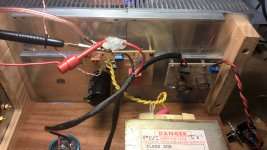
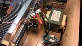
I encountered a similar situation. I originally set up my Mofo with Hammond chokes and then changed over to Lundahl chokes. During the change I fried an IRFP250. I didn’t know why that happened and just assumed it got too hot during bias set up. But, after following your journey I think it was how I disconnected the power during bench setup. When installed in the chassis there is a CRC filter just before entering the MoFo board, even if power was pulled from the dc plug, power down is slow because the caps are slowly discharging.
On the bench there was no filter, SMPS directly connected to MoFo. I probably fried it then by pulling the dc plug instead of the wall plug.
I too am seeing things more clearly 🙂

Pass DIY Addict
Joined 2000
Paid Member
Vunce - how large is your CRC? I thought that SMPS didn't like to have big caps attached. I did see a simple circuit that Nelson shared with a cap and a diode making the cap more SMPS-friendly. I'm thinking a cap large enough to bring a 20V 2A PSU down more gracefully needs to be rather large.
Zen: I'll have to look through my 9V1 zeners and see if I have any 1w versions that I can run in series to get me 18v as a temporary measure.
Zen: I'll have to look through my 9V1 zeners and see if I have any 1w versions that I can run in series to get me 18v as a temporary measure.
Last edited:
- Home
- Amplifiers
- Pass Labs
- Build This MoFo!