It's a IRFP240
Sorry to bring up an old post.
Frank, Q2 can't be irfp240, your schematic showing Q2 as BJT, Q1 is MOSFET. What is Q2? 😕
I would probably have got some quite expensive "Jensen Capacitors" audio grads caps (as I did with the ACA) so all in all there is not a huge price difference. An output cap will never improve the sound. At best it will be neutral? ….now the simple circuit will be simpler. I can also omit R5 which is a bleeder resistor for C2 I assume?8 mOhm weight 20 Kg
to remove a cap I have to buy a mule

my output cap is a Panasonic NHG .I would probably have got some quite expensive "Jensen Capacitors" audio grads caps (as I did with the ACA) so all in all there is not a huge price difference. An output cap will never improve the sound. At best it will be neutral? ….now the simple circuit will be simpler. I can also omit R5 which is a bleeder resistor for C2 I assume?
I would make a change just to put a cap in polypropylene but also with those I would get to 20kg of cap mkp.
And perhaps at that point the 20Kg inductance is better.
I would like a simpler solution to not ask for help from the mule ..... but I do not think it exists.
It is necessary to choose the lesser evil in my opinion
to EmeryBB, sorry my mistake, I use a BC547b, but any small signal transistor will work. It is just used to lower the impedance in the bias.
MEPER
With a core that big you will also be working in just a small part of the cores magnetic hysteresis; thus, it will be more linear. Love to see your project.
With a core that big you will also be working in just a small part of the cores magnetic hysteresis; thus, it will be more linear. Love to see your project.
my output cap is a Panasonic NHG .
I would make a change just to put a cap in polypropylene but also with those I would get to 20kg of cap mkp.
And perhaps at that point the 20Kg inductance is better.
I would like a simpler solution to not ask for help from the mule ..... but I do not think it exists.
It is necessary to choose the lesser evil in my opinion
I have seen these very large high voltage MKPs. Usually they are 800 VDC types and made for DC filtering? …..they are quite expensive. A 6800 uF may be 500 - 1000 USD?
I few threads back I say one MoFo solution with one of these big MKPs hanging on the heatsink.
They should be ready for pickup in week 29......so we will see. I have asked for a box for each choke for carry them into the trunk of the car and from the car to the apartment. I think the choke will also protect the speakers against failure in the amp causing high DC voltage at the output. If not the rail fuse burns the MOFSET will act as a fuse? The choke and speaker will probably survive.MEPER
With a core that big you will also be working in just a small part of the cores magnetic hysteresis; thus, it will be more linear. Love to see your project.
It seems that a heatsink like this will fit the MoFo PCB?
ABL Components, Koleplade, 0.11degC/W, Printmontering, 200 x 125 x 135mm | 750AB2000B | RS Components
The heatsink has 80mm between the two mounting rails at the front. It looks like it is same type of heatsink used in the very first thread.
ABL Components, Koleplade, 0.11degC/W, Printmontering, 200 x 125 x 135mm | 750AB2000B | RS Components
The heatsink has 80mm between the two mounting rails at the front. It looks like it is same type of heatsink used in the very first thread.
It seems that a heatsink like this will fit the MoFo PCB?
ABL Components, Koleplade, 0.11degC/W, Printmontering, 200 x 125 x 135mm | 750AB2000B | RS Components
The heatsink has 80mm between the two mounting rails at the front. It looks like it is same type of heatsink used in the very first thread.
Holy c@$p.... 100 € for a heatsink...
But yes, 3.15" × 2.54 = 80mm , so the pcb fill fit heatsink perfectly
Last edited:
Yes, it cost some money……...it is the 200 mm in height version. It also exist in a 100 mm version for about haft the price (0.19 degC/W). Think the 200 mm if a good "match" for the choke. On top of that 25% Danish tax is added.
Will this IRFP250 version work for the MoFo?
Vishay N-Kanal, MOSFET, 30 A 200 V, 3 ben, TO-247AC IRFP250PBF | IRFP250PBF | RS Components
Will this IRFP250 version work for the MoFo?
Vishay N-Kanal, MOSFET, 30 A 200 V, 3 ben, TO-247AC IRFP250PBF | IRFP250PBF | RS Components
Hi MEPERI have seen these very large high voltage MKPs. Usually they are 800 VDC types and made for DC filtering? …..they are quite expensive. A 6800 uF may be 500 - 1000 USD?
I few threads back I say one MoFo solution with one of these big MKPs hanging on the heatsink.
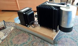
you're probably referring to my realization of the Mofo. I used that big polypropylene cap on the power supply downstream of the SMPS MeanWell.
Those big cap I paid them very little money (I also put the link for those interested ..... surplus material but in perfect condition).
I have 8 more, that I would try to use in out but being from 500uF / 900V to 6000uF I do not get there.
I took them to experiment ..... The next experiment will be using Salas ultraBiB 1.3 instead of the SMPS + MKPcaps.
My Mofo Big on attach.
PS: the link of caps.....500uF 900Vdc capacitor ISKRA KNG2047 polypropylene
Attachments
Last edited:
Ok....so it was used for SMPS filtering and not as output cap. Could also be interesting to know how such a cap type compare against the standard E-cap. From new at RS components they are expensive.Hi MEPER
you're probably referring to my realization of the Mofo. I used that big polypropylene cap on the power supply downstream of the SMPS MeanWell.
Those big cap I paid them very little money (I also put the link for those interested ..... surplus material but in perfect condition).
I have 8 more, that I would try to use in out but being from 500uF / 900V to 6000uF I do not get there.
I took them to experiment ..... The next experiment will be using Salas ultraBiB 1.3 instead of the SMPS + MKPcaps.
My Mofo Big on attach.
Ok.....then I have control on most components. I wonder what would happen if I went for 3A bias......now the big choke can handle it and probably also the heatsink. This could be some experiments but first I need to have it built. It is an interesting concept.Yes work fine 🙂
CautionOk.....then I have control on most components. I wonder what would happen if I went for 3A bias......now the big choke can handle it and probably also the heatsink. This could be some experiments but first I need to have it built. It is an interesting concept.
the maximum current that supports the Hammond 193V inductor is 3A.
the bias should not exceed 2.5A
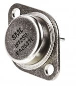
Mosfet's in TO-3 metal can package look great but is not easy to find good vintage transistors source.Ok.....then I have control on most components.
Lot of fakes : eBay , Aliexpress etc.
Official distributor´s : Mouser , Digi-Key, RS or Farnell stock are genuine stuff
but TO-3 is frequently not available
https://docs-emea.rs-online.com/webdocs/156f/0900766b8156f429.pdf
Good luck 🙂
Attachments
I will be using a custom made choke. I handles 3A easy so not the choke which is the limit. But I start with 2.5A and see how it performs......Caution
the maximum current that supports the Hammond 193V inductor is 3A.
the bias should not exceed 2.5A
Mosfet's in TO-3 metal can package look great but is not easy to find good vintage transistors source.
Lot of fakes : eBay , Aliexpress etc.
Official distributor´s : Mouser , Digi-Key, RS or Farnell stock are genuine stuff
but TO-3 is frequently not available
https://docs-emea.rs-online.com/webdocs/156f/0900766b8156f429.pdf
Good luck 🙂
The heatsink I have in mind does not fit a TO-3 very well…...I think....so think it will be the modern housing. For TO-3 you need a kind of rail/bracket to mount them and then mount the rail to the heatsink. TO-3 looks nice…..I also think they can transfer the heat a little better than the plastic type housing.
to EmeryBB, sorry my mistake, I use a BC547b, but any small signal transistor will work. It is just used to lower the impedance in the bias.
Cheers Frank.

- Home
- Amplifiers
- Pass Labs
- Build This MoFo!