When discussing inductance, remember:
The output of the Source Follower is VERY low impedance. Most of the foibles of iron-core inductors vanish when driven low-Z.
Inductance will drop with frequency, but inductive Reactance rises with frequency! Iron-core coils retain enough inductance to be high impedance over the audio range. When they stop rising, we call it Capacitive reactance. I'd expect the proposed lump to be say 2,000pFd stray capacitance. At 8 Ohms, MHz!
What lack of infinite impedance in the choke does is limit Power Bandwidth, not frequency response. 50mH starts to steal a lot of energy from 8 Ohms at and below 27 Hz. You seriously don't expect <30Hz response from a 12 Watt amplifier. No domestic loudspeaker makes enough 30Hz to hear with 10 Watts, and no headphone needs anywhere near all 12 Watts.
Wow, that was fast! Well done. Enjoy🙂
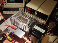
2.5 A bias x 1.12 Ohm R of L1 = 2.8 DCV across L1
Every parameters match perfectly the criteria from article about Big MoFo.
Feel Gooood
Attachments
This is a great design to test the IRFP7430.
I am sure most of you will be quite surprised by the change of character and subjective increase in muscle and vitality.
I have tested many different mosfet source followers with many different mosfets, and the IRFP7430 is by far the best sounding mosfet in this kind of simple design IMHO.
Keep the supply voltage below 20 volts, since you don't want to exceed the 40 volt rating of the IRFP7430.
Cheers,
Johannes
The IRFP7430 has a high transconduttance, but an input capacitance of 1420pF. this could be a problem?
I enjoyed the article very much. In style it reminded me of Corey Grreenberg's Aunt Corey's Passive Buffered Preamp series from Stereophile.
A question about the laptop charger: does anyone sell those replacement jacks?
If you mean the 2.5mm type, I've seen those in the Mouser catalog, and on Amazon. 🙂
When discussing inductance, remember:
The output of the Source Follower is VERY low impedance. Most of the foibles of iron-core inductors vanish when driven low-Z.
Inductance will drop with frequency, but inductive Reactance rises with frequency! Iron-core coils retain enough inductance to be high impedance over the audio range. When they stop rising, we call it Capacitive reactance. I'd expect the proposed lump to be say 2,000pFd stray capacitance. At 8 Ohms, MHz!
What lack of infinite impedance in the choke does is limit Power Bandwidth, not frequency response. 50mH starts to steal a lot of energy from 8 Ohms at and below 27 Hz. You seriously don't expect <30Hz response from a 12 Watt amplifier. No domestic loudspeaker makes enough 30Hz to hear with 10 Watts, and no headphone needs anywhere near all 12 Watts.
Thanks for the explanation. I think I have enough to go on that I will order these Hammonds to try out.
The IRFP7430 has a high transconduttance, but an input capacitance of 1420pF. this could be a problem?
Has more need of low impedance source.
Thank you Michael Rothacher for a great article and a great project!
Thumbs up for this project!!!
I love the extreme simplicity and I know it can sound absolutely fantastic!!!
Regards,
Johannes
Thumbs up for this project!!!
I love the extreme simplicity and I know it can sound absolutely fantastic!!!
Regards,
Johannes
Hi MR! Can you tell me what happen if I replace 193T by 193U (the same current but higher inductance and higher Rdc)?
Thanks!
Thanks!
You'll lose some output capability due the the extra voltage you'll be dropping across the higher DCR and a little bit of damping factor. You can adjust by using a higher supply. I'd use a 24V switcher and run the bias a little closer to the full 2A. You'll probably get a distortion performance boost from the extra Henries and higher bias. I say go for it. 🙂
Dear Mr. Michael,
Very nice , simple and interesting project.
I would think it would sound wonderful too.
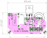
I just couldnt control my urge to make a simple layout😀. So here is a first cut, 'MO' of 'MOFO' is not exactly at center, but still.....
regards
Prasi
Very nice , simple and interesting project.
I would think it would sound wonderful too.
I just couldnt control my urge to make a simple layout😀. So here is a first cut, 'MO' of 'MOFO' is not exactly at center, but still.....
regards
Prasi
Attachments
Hello kitty pcb ? is for ZM ?😀
hello nicoch58,
are you making a joke? it isnt even fit for a retard! I am sure ZM isnt one. So, next time before posting comments that dont add value and are nowhere near the spirit of the forum, stop to think for a moment🙂.
regards
Prasi
Member
Joined 2009
Paid Member
maybe some interest in some of the pre amp options from the choke loaded SEWA amplifier which could be applied here?
SEWA - Seven Watt Amplifier
SEWA - Seven Watt Amplifier
- Home
- Amplifiers
- Pass Labs
- Build This MoFo!