The trim pot on the capMx sets the dropout voltage. Set it so the output is .5v less than the input voltage.
Alas, it's a lot less fussy to just insert a .1 ohm resistor at the + power input and measure that. I soldered mine right to the jack. 🙂
Alas, it's a lot less fussy to just insert a .1 ohm resistor at the + power input and measure that. I soldered mine right to the jack. 🙂
Great trick and thanks for reminding us. I have some 1%, 0.1R resistors that's perfect for this use... 🙂
Cheers,
Dennis
If you have pics of your MoFo, please post them. 🙂
Getting antsy to hear this thing! Re-read the article at work to calm down. 🙂
Counting down the hours until construction can continue on the MoFo!
Getting antsy to hear this thing! Re-read the article at work to calm down. 🙂
Counting down the hours until construction can continue on the MoFo!
Well drats no .1R here.
See my MoFo post about 2.5A bias and inductor mesured voltage
Build This MoFo!
🙂
If you have pics of your MoFo, please post them. 🙂
Getting antsy to hear this thing! Re-read the article at work to calm down. 🙂
Counting down the hours until construction can continue on the MoFo!
Sure, I'll take some pics tomorrow. 🙂
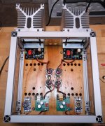
Vunce, here is a dry fit of the components. My plan is to drill some .5" holes around the north and south ends of the chokes. The top cover will feature a brass grill across the top for ventilation.
drpro, so you are running the commercial cap mx boards, and a DC boost converter for each channel? Is yours a big MoFo or the 19V version? Also, please enlighten as to the four caps located between the chokes (this would be my first use of a cap multiplier if I proceed, so I'm trying to make sure I understand).
🙂
Closer now to the finish line. Initial wiring completed, back paneled drilled and mounted, awaiting painting, labels and final wiring to the various connectors.
Voltages throughout have been adjusted and bias is set for the 193V chokes.
Brian, cap MX and DC boosters from Ebay. Each pair of cap/resistor combos are to remove any of the noise that might make it though the power supply chain, which is a 24vdc 5amp Meanwell switched supply, DC booster, cap MX and finally the CRC combos. I take no credit for this approach, others have recommended this and XRK is the wizard of switched supplies and cap MX. Plus the DC boosters allow you to dial in the voltage you need. About 4usd each.
I am going the big MoFo thus the need for the bigger chokes and larger heat sinks.
David
Attachments
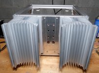
Yep, minimal sides makes the wiring much easier!!
Yes it does! I had a heck of a time connecting the input and output wires because the boards were close to the side panels.
Looks great David🙂
Did the capMx mosfets cool down a bit after adjustment?
Looks great DrPro. The DC booster PCB can get hot at these currents - generally they are screwed to a metal surface as a heatsink. They PCB is metal for this reason. The metal board itself is insulated. If you have a metal panel somewhere - it would be good to bolt the dC boost to. If not at least add a local sheet of aluminum or other small local heatsink to it. Even a small heatsink from a computer GPU cooler stick on with white RTV silicone can work.
Thanks for the tip Vunce, cap MX much cooler, going to leave the larger sinks because I can!!
I hadn't noticed a major rise in heat on the DC boosters even after a couple of hours on. I have some thick aluminum plates I could attach to the bottom, if you think that would be enough X. If not I can mount them on edge and some sink material.
Thanks for all
David
I hadn't noticed a major rise in heat on the DC boosters even after a couple of hours on. I have some thick aluminum plates I could attach to the bottom, if you think that would be enough X. If not I can mount them on edge and some sink material.
Thanks for all
David
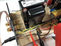
Here you go, Vince. Have a speaker or dummy load connected when you're doing this. 🙂
Article text:
"Alternatively, you can insert a .1 ohm 3W resistor in series with the positive terminal of your PSU and measure the voltage there, e.g. .1 x 1.7 = .17 volts."
Article text:
"Alternatively, you can insert a .1 ohm 3W resistor in series with the positive terminal of your PSU and measure the voltage there, e.g. .1 x 1.7 = .17 volts."
Attachments
Last edited:
Here you go, Vince. Have a speaker or dummy load connected when you're doing this. 🙂
AHHA! So connecting the speaker will save the capMx from getting toasted.
Good thing I always purchase extras 😀
- Home
- Amplifiers
- Pass Labs
- Build This MoFo!