Re: BestPentode
I was thinking a 6F12P would be a good candidate, since it has a high gm RF pentode and frame grid high mu triode in one 9pin mini bottle. I did a search and found bondini's circuit using BestPentode > passive RIAA > Triode. kevinkr recommended adding a MOSFET source follower on the output. This could be re-jiggered to put half the EQ in a feedback loop around the output triode (anode follower-style).
Phonospud – sandy Muscovite Micro with a pentode first stage
I need to read more about the BestPentode. I don't understand it well enough to design my own, yet...
I am following (reading) this thread with great interest.
Your new schematic suggestion is very nice, but......
I am curious why you, in stead of just using a cathode resistances, use a diodes instead. What is the purpose?
The equation for figuring Miller C in a triode is
Cgk + Cga (A + 1)
Of course in a pentode both the anode and g2 are strapped together. Does that mean the triode Cga is now Cg1-a+g2? I don't know. I've asked but no-one seems to know for sure.
In the data sheet I have, interelectrode capacitances are listed as
triode input = 4.6pF (add 1pF for strays)
triode transfer = 1.6pF (whatever "triode transfer" means -- I don't know)
Let's assume "triode transfer" is Cga and "triode input" is C of grid to all other electrodes (approx = Cgkh)
The data sheet says the mu of the triode = 100, and I think the g2-a mu of the pentode is also 100. That would mean the trioded pentode's mu is also around 100. Figure on a real world gain of about 60.
Adding 1pF to each for strays...
5.6pF + 2.6pF(61) = 164pF
That seems about right, since a 12AX7's Cin would be >200pF.
Anyhow, the best high mu triodes for low capacitance are known. EC97, 6GK5, 6HQ5, 6HA5, PC900 and a few others like them.
The downsides of these triodes are high THD, variability, and sometimes microphonics.
--
Last edited:
Code:
I am curious why you, in stead of just using a cathode resistances, use a diodes instead. What is the purpose?I also noticed that the sch you posted #76, the pentode is operating at x% utra-linear so bewared that the Miller effect capacitance is even greater than our triode connected mode.
That's Frank Blohbaum's BestPentode circuit. I don't claim to understand it well at all, but I have not found any mention of that circuit putting the pentode in an ultralinear-ish mode of operation (intermediate between pentode and triode modes).
Frank Blohbaum first described BestPentode operation in Issue 0 of Linear Audio (Jan Didden's magazine).
--
Frank Blohbaum first described BestPentode operation in Issue 0 of Linear Audio (Jan Didden's magazine).
--
That's Frank Blohbaum's BestPentode circuit. I don't claim to understand it well at all, but I have not found any mention of that circuit putting the pentode in an ultralinear-ish mode of operation (intermediate between pentode and triode modes).
Frank Blohbaum first described BestPentode operation in Issue 0 of Linear Audio (Jan Didden's magazine).
--
Looking at that circuit diagram I indeed do not see any ultra-linear effect. It is a "dead quiet" DC coupling from the plate DC voltage to the screen grid. Apart from that I do not understand why it is not simply a decoupled voltage divider from supply voltage to the screen grid.
Last edited:
bondini's Phonospud, in post #76, isn't strictly BestPentode because the cascoding transistor's base DC reference comes voltage-divided from the anode rather than B+. But for signal, the base is still referenced to ground, so not ultra-linear.
All good fortune,
Chris
All good fortune,
Chris
bondini's Phonospud, in post #76, isn't strictly BestPentode because the cascoding transistor's base DC reference comes voltage-divided from the anode rather than B+. But for signal, the base is still referenced to ground, so not ultra-linear.
All good fortune,
Chris
As I wrote : a "dead quiet" voltage. Which is for AC a zero voltage to "ground"
I can see something in that transistor coupling to the screen grid if its collector is connected to the supply in stead of the plate. Then it follows the DC plate voltage and supplies the screen grid current without affecting the DC plate current.
But i may see that wrongly of course.
But i may see that wrongly of course.
On the plate of the first tube you will see DC and AC. Make a simulation in LTspice if you want to check for yourself.
Regards, Gerrit
Regards, Gerrit
On the plate of the first tube you will see DC and AC. Make a simulation in LTspice if you want to check for yourself.
Regards, Gerrit
Yes, but at the transistor base there is only a DC voltage left. It is completely decoupled.
The screen and transistor forms a cascode pairs, the transistor is the upper triode while the screen is lower triode. The bias is provided by the voltage divider to the base (grid1), and bypass just like the ordinary cascode. So this (pseudo) pentode has more gain than the original pentode , the screen now acting as lower cascode the gain affect the gain of new pseudo patentode and original real pentode, is this right? It there for a few years but I just heard about it. Maybe LTspice can reveal the truth.
baddiwad – lab jc
My first phono pre
baddiwad – lab jc
My first phono pre
Gain of a pentode is a product of g1g2 transconductance and load impedance, so is very similar in BestPentode. The real advantage of Blohbaum's cascoded G2 is in minimizing partition noise, by adding G2 current back into the anode current. merlinb made an excellent analysis of noise and gain issues with BestPentode in Linear Audio Vol. 10.
All good fortune,
Chris
All good fortune,
Chris
This discussion is great, but it's gone way over my head. I can't do the math to visualize what the BJT is doing between g2 and a of the pentode, but I can throw everything into SPICE and see what the voltages etc. look like.
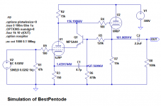
I took F. Blohbaum's schematic from his ETF presentation and adapted it to tube models I know how to work with, namely a 6J9P model courtesy of Wayne Clay, and Adrian Immler's i4 6N6P model (for the cathode follower/output buffer). I've attached the schematic.
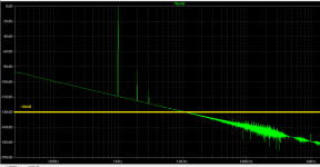
The results are pretty astonishing. I get 70X gain, extremely low noise, and extremely low THD (only 0.006% at 1V RMS output 1kHz, which looks far 2G2BT, if you ask me).
I'll also attach the .asc so Koonw can have a go at it, since he's better at LTspice than I am. Koonw, what do you see?
I took F. Blohbaum's schematic from his ETF presentation and adapted it to tube models I know how to work with, namely a 6J9P model courtesy of Wayne Clay, and Adrian Immler's i4 6N6P model (for the cathode follower/output buffer). I've attached the schematic.
The results are pretty astonishing. I get 70X gain, extremely low noise, and extremely low THD (only 0.006% at 1V RMS output 1kHz, which looks far 2G2BT, if you ask me).
I'll also attach the .asc so Koonw can have a go at it, since he's better at LTspice than I am. Koonw, what do you see?
Attachments
Last edited:
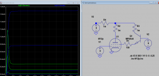
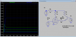
I sim the pseudo pentode, the gain seem to be doubled by looking at the pentode and screen spacing, the zero bias Ia drops by half. The zero bias Ia can reach the same as original when transistor is biased at 20V but the entire curves are shifted right by 20V, which is the behavior of pseudo pentode. I wouldn't call it "best" as it's pseudo or pretend. It maybe good when biased low for small signal, but note sure for larger signal where the Ia appears restricted.
Attachments
Last edited:
The LTspice models I used in post 95's .asc
MPSA44
Adrian Immler's 6N6P.i4
Wayne Clay's (I think) 6J9P
MPSA44
Code:
.MODEL MPSA44 NPN IS=186.36E-15 BF=60.596 VAF=9.2909 IKF=.1107 ISE=1.8215E-12 NE=1.5767 BR=499.50 VAR=100 IKR=19.980 ISC=1.2445E-6 NC=2.9970 NK=.78598 RE=490.00E-6 RB=5.2315 RC=1.0000E-3 CJE=104.69E-12 VJE=1.0643 MJE=.41036 CJC=9.8356E-12 VJC=.35 MJC=.28065 TF=5.1798E-9 XTF=3.2122 VTF=25.040 ITF=.19258 TR=6.837E-6Adrian Immler's 6N6P.i4
Code:
*6N6P LTspice model based on the generic triode model from Adrian Immler, version i4
*A version log is at the end of this file
*100h BurnIn of 4 Novosibirsk factory tubes, sample selection and measurements done in Febr. 2021
*Params fitted to the measured values by Adrian Immler, Febr. 2021
*The high fit quality is presented at adrianimmler.simplesite.com
*History's best of tube decribing art (plus some new ideas) is merged to this new approach.
*@ neg. Vg, Ia accuracy is similar to Koren models.
*@ small neg. Vg, the "Anlauf" current is considered.
*@ pos. Vg, Ig and Ia accuracy is on a unrivaled level.
*This offers new simulation possibilities like bias point setting with MOhm grid resistor,
*Audion radio circuits, low voltage amps, guitar distortion stages or pulsed stages.
*               anode (plate)
*               | grid
*               | | cathode
*               | | |
.subckt 6N6P.i4 A G K
+ params:
*Parameters for the space charge current @ Vg <= 0
+ mu   = 20.3 ;Determines the voltage gain @ constant Ia
+ rad  = 1k1  ;Differential anode resistance, set @ Iad and Vg=0V
+ Vct  = -0.85;Offsets the Ia-traces on the Va axis. Electrode material's contact potential
+ kp   = 90   ;Mimics the island effect
+ xs   = 1.60 ;Determines the curve of the Ia traces. Typically between 1.2 and 1.8
*
*Parameters for assigning the space charge current to Ia and Ig @ Vg > 0
+ kB   = 0.4  ;Describes how fast Ia drops to zero when Va approaches zero.
+ radl = 10   ;Differential resistance for the Ia emission limit @ very small Va and Vg > 0
+ tsh  = 5    ;Ia transmission sharpness from 1th to 2nd Ia area. Keep between 3 and 20. Start with 20.
+ xl   = 1.2  ;Exponent for the emission limit
*
*Parameters of the grid-cathode vacuum diode
+ kvdg  = 27  ;virtual vacuumdiode. Causes an Ia reduction @ Ig > 0.
+ kg = 590    ;Inverse scaling factor for the Va independent part of Ig (caution - interacts with xg!)
+ Vctg = -0.75;Offsets the log Ig-traces on the Vg axis. Electrode material's contact potential
+ xg   = 1.4  ;Determines the curve of the Ig slope versus (positive) Vg and Va >> 0
+ VT   = 0.11 ;Log(Ig) slope @ Vg<0. VT=k/q*Tk (cathodes absolute temp, typically 1150K)
+ kVT=0.1     ;Va dependant koeff. of VT
+ Vft2 = 0.0 gft2 = 20 ;finetunes the gridcurrent @ low Va and Vg near zero
*
*Parameters for the caps
+ cag  = 3p5  ;From datasheet
+ cak  = 1p85 ;From datasheet
+ cgk  = 4p4  ;From datasheet
*
*special purpose parameters
+ os = 1      ;Overall scaling factor, if a user wishes to simulate manufacturing tolerances
*
*Calculated parameters
+ Iad = {100/rad} ;Ia where the anode a.c. resistance is set according to rad.
+ ks = {pow(mu/(rad*xs*Iad**(1-1/xs)),-xs)} ;Reduces the unwished xs influence to the Ia slope
+ ksnom = {pow(mu/(rad*1.5*Iad**(1-1/1.5)),-1.5)} ;Sub-equation for calculating Vg0
+ Vg0 = {Vct + (Iad*ks)**(1/xs) - (Iad*ksnom)**(2/3)} ;Reduces the xs influence to Vct.
+ kl = {pow(1/(radl*xl*Ild**(1-1/xl)),-xl)} ;Reduces the xl influence to the Ia slope @ small Va
+ Ild = {sqrt(radl)*1m} ;Current where the Il a.c. resistance is set according to radl.
*
*Space charge current model
Bggi GGi 0 V=v(Gi,K)+Vg0 ;Effective internal grid voltage.
Bahc Ahc 0 V=uramp(v(A,K)) ;Anode voltage, hard cut to zero @ neg. value
Bst   St 0 V=uramp(max(v(GGi)+v(A,K)/(mu), v(A,K)/kp*ln(1+exp(kp*(1/mu+v(GGi)/(1+v(Ahc)))))));Steering volt.
Bs    Ai K I=os/ks*pow(v(St),xs) ;Langmuir-Childs law for the space charge current Is
*
*Anode current limit @ small Va
.func smin(z,y,k) {pow(pow(z+1f, -k)+pow(y+1f, -k), -1/k)} ;Min-function with smooth trans.
Ra  A Ai 1
Bgl Gi A I=min(i(Ra)-smin(1/kl*pow(v(Ahc),xl),i(Ra),tsh),i(Bgvd)*exp(4*v(G,K))) ;Ia emission limit
*
*Grid model
Bvdg G Gi I=1/kvdg*pwrs(v(G,Gi),1.5) ;Reduces the internal effective grid voltage when Ig rises
Rgip G Gi 1G ;avoids some warnings
Cvdg G Gi 0p1;this small cap improves convergence
.func fVT() {VT*exp(-kVT*sqrt(v(A,K)))}
.func Ivd(Vvd, kvd, xvd, VTvd)  {if(Vvd < 3, 1/kvd*pow(VTvd*xvd*ln(1+exp(Vvd/VTvd/xvd)),xvd), 1/kvd*pow(Vvd, xvd))} ;Vacuum diode function
Bgvd Gi K I=Ivd(v(G,K) + Vctg, kg/os, xg, fVT())
.func ft2() {gft2*(1-tanh(3*(v(G,K)+Vft2)))} ;Finetuning-func. improves ig-fit @ Vg near -0.5V, low Va.
Bgr Gi Ai I=ivd(v(GGi),ks/os, xs, 0.8*VT)/(1+ft2()+kB*v(Ahc));Is reflection to grid when Va approaches zero
Bs0 Ai K  I=ivd(v(GGi),ks/os, xs, 0.8*VT)/(1+ft2()) - os/ks*pow(v(GGi),xs) ;Compensates neg Ia @ small Va and Vg near zero
*
*Caps
C1 A G {cag}
C2 A K {cak}
C3 G K {cgk}
.ends
*
*Version log
*i1 :Initial version
*i2 :Pin order changed to the more common order „A G K“ (Thanks to Markus Gyger for his tip)
*i3 :bugfix of the Ivd-function: now also usable for larger Vvd
*i4: Rgi replaced by a virtual vacuum diode (better convergence). ft1 deleted (no longer needed)
;2 new prarams for Ig finetuning @ Va and Vg near zero. New emission skaling factor ke for aging etc.
Wayne Clay's (I think) 6J9P
Code:
**** 6J9P_4 ******************************************
* Created on 11/25/2013 00:58 using paint_kit.jar 2.6
* Model Paint Tools: Trace Tube Parameters over Plate Curves, Interactively
* Plate Curves image file: 6j9p_4.jpg
* Data source link:
*----------------------------------------------------------------------------------

.SUBCKT 6J9P 1 4 2 3 ; P K G2 G1
+ PARAMS: CCG=8.5P CGP=0.03P CCP=3P RGI=2000
+ MU=55.9 KG1=280.9 KP=369.1 KVB=23.1 EX=1.49 KG2=400
* Vp_MAX=480 Ip_MAX=40 Vg_step=0.5 Vg_start=-0.5 Vg_count=5
* Rp=1600 Vg_ac=23.5 P_max=7.5 Vg_qui=-23.4 Vp_qui=240 UL=0.469 EG2=139.2
* X_MIN=73 Y_MIN=50 X_SIZE=365 Y_SIZE=256 FSZ_X=1032 FSZ_Y=742 XYGrid=false
* showLoadLine=n showIp=y isDHT=n isPP=n isAsymPP=n isUL=n showDissipLimit=n
* showIg1=y gridLevel2=n isInputSnapped=n
* XYProjections=n harmonicPlot=y harmonics=y
*----------------------------------------------------------------------------------
RE1 7 0 1MEG ; DUMMY SO NODE 7 HAS 2 CONNECTIONS
E1 7 0 VALUE= ; E1 BREAKS UP LONG EQUATION FOR G1.
+{V(4,3)/KP*LOG(1+EXP((1/MU+V(2,3)/V(4,3))*KP))}
G1 1 3 VALUE={(PWR(V(7),EX)+PWRS(V(7),EX))/KG1*ATAN(V(1,3)/KVB)}
G2 4 3 VALUE={(EXP(EX*(LOG((V(4,3)/MU)+V(2,3)))))/KG2}
RCP 1 3 1G ; FOR CONVERGENCE
C1 2 3 {CCG} ; CATHODE-GRID 1
C2 1 2 {CGP} ; GRID 1-PLATE
C3 1 3 {CCP} ; CATHODE-PLATE
R1 2 5 {RGI} ; FOR GRID CURRENT
D3 5 3 DX ; FOR GRID CURRENT
.MODEL DX D(IS=1N RS=1 CJO=10PF TT=1N)
.ENDS
Last edited:
visualize what the BJT is doing between g2 and a of the pentode
If you imagine it as a pentode of very very high transconductance and ignore base current (quite reasonable at beta of 100 or whatever) then the BJT becomes an active conveyor of current, with very low impedance at the G2 end and very high impedance at the anode end. Essentially all of G2 current is restored to the original cathode current stream, eliminating partition noise.
Gain of 70 implies a valve transconductance of 15.5mA/V, which sounds a little high for just under 10mA cathode current, but possible. Best noise performance will depend on a balance between Johnson/Nyquist/thermal noise, which improves with higher current, and excess (1/f) noise, which degrades with higher current. A good phono stage's noise can be dominated by noise from the source plus 47K load impedance, but takes some effort, and excess noise is a wild card by definition. If you don't need the 37dB gain, you might want to try somewhat lower cathode current.
All good fortune,
Chris
Last edited:
I thought that in a phono preamp, you want as much gain as you can get in the first stage, so that you're not amplifying more noise than signal in subsequent stages.
Or are you thinking of using a BestPentode as part of a feedback pair?
Sorry, so much has been discussed, I'm beginning to get lost...
PS - I'll bet the high gm to Ip ratio is due to an optimistic model, or maybe the model was based on a set of plate curves from a very strong example.
Or are you thinking of using a BestPentode as part of a feedback pair?
Sorry, so much has been discussed, I'm beginning to get lost...
PS - I'll bet the high gm to Ip ratio is due to an optimistic model, or maybe the model was based on a set of plate curves from a very strong example.
Last edited:
I got the same Thd result as you, so your setting is good for your need and application. But that is your target if you're happy with it and good, you shouldn't worry, esp we don't invent this ourselves.
On the other hand for my application if also need more head room, I readjust the transistor bias R6 down to 160k, so this gives me this:
in 0.9v out 60v. thd 1.5%
in 0,0202v out 1.5V,Thd:: 0.028156%(0.027936%)
If you don't need headroom your setting is fine, but be awared where you draw the boarder line to be acceptable. I would expect more than 60v head room it clips already. Where does the distortion come from then?! Is it reveal in my previous curve posted?
Last edited:
- Home
- Amplifiers
- Tubes / Valves
- Build Phono Preamp