Even phono equalizers need headroom. Using valves at several hundred volt B+ we can usually ignore it as an issue, but guys using +/- 15VDC opamps have to scramble to keep from clipping on (very rare) +30VU peaks or small boulders in the groove.
Best noise performance *and* best overload margin comes from a single long loop feedback with RIAA from output back to input. This is unpopular now, and blamed for the fall of civilization as we knew it, but is still true. FWIW. I think it went out of favor when the Lipshitz paper came out in 1979 and everybody realized how hard they'd have to work to get under the (also new) .1dB error limit. But that was BC (before computers).
All good fortune,
Chris
I attributed it to Morgan Jones earlier, but it was actually Merlin Blencowe who wrote a critique of the classic 12AX7-based 'ring of two' or 'ring of three' RIAA preamp circuits of yore. If I understand what he wrote, he believes there is not enough open loop gain in vacuum tube circuits to achieve accurate RIAA EQ, so inevitably it becomes necessary to fudge the component values to compensate for shortcomings due to lack of open loop gain, so as to arrive at a good RIAA curve. Meanwhile, inside the loop, the active elements (tubes) are reaching limits that compromise performance. He's quick to point out that it's relatively trivial to realize the RIAA curve completely within a global NFB loop using opamps, due to the immense open loop gain available, and comes to the conclusion that implementing RIAA EQ completely within a NFB loop is best done with transistors, while tubes should be used with passive or half-active/half-passive EQ networks.
Morgan Jones, in his book, dismisses classic RIAA preamps as not worth investigating. He glosses over that really quickly, and immediately launches into topologies using passive networks.
Obviously you don't agree with them, and I'm interested why not.
I'm tempted to try a half-passive/half-active RIAA to find out how it sounds with EQ implemented in NFB. It might be great.
Also, I was reading Bruno Putzey's paper on NFB (The F-Word) from Linear Audio. He maintains (as does JC Morrison and others) that if you're going to use NFB, best results come if one starts with a circuit that has a lot of open loop gain, and uses a lot of NFB. The feedback pair using feedback over a pair of cascaded 12AT7s probably qualifies as that kind of thing. Maybe run a pentode into a triode for that much more gain? Or a BestPentode into a triode with the NFB around them?
Anyway, all that is a bit beyond me. I'm comfortable with the 12AT7 feedback pair idea because I believe I fully comprehend it. The BestPentode is beyond me right now, but perhaps after more reading and thinking I'll come to an understanding. It may take some time.
Thanks for your input, though. I've learned a lot these last couple of days, and I'm grateful for that.
I'm not really advocating for the classic long loop feedback model for valve amplifiers of any sort, just pointing to it as a limiting condition. For a +/- 15VDC opamp phono stage, anything else is foolish (but we still see a lot of it).
It is completely possible to get arbitrarily close to perfect RIAA playback response with finite gain amplifiers and feedback eq, but it's a giant pain without computer assistance. That, and fear of the F-word, have, I believe, caused the current fashion trend. But I'll shut up about that.
The Baxandall/Putzeys models are built on pathological cases. Another reason to keep everything as intrinsically linear as possible, is my take-away. They really don't apply to 12AX7s and 6SN7s properly operated. Very simple to prove to oneself, even in a computer model.
My personal take is that your current plan for two gain stages separated by RIAA eq is about as optimum as things get in this world, although I'd personally put the 75uS pole in anode follower feedback in the last stage. Call me old fashioned, but don't call me late for dinner.
All good fortune,
Chris
My personal take is that your current plan for two gain stages separated by RIAA eq is about as optimum as things get in this world, although I'd personally put the 75uS pole in anode follower feedback in the last stage.
Well, thanks, that does sound encouraging.
I bodged together a little 6DJ8 anode follower set to 6dB gain, with a horrid +160V B+ and AC heater, and it actually sounds kind of pleasant. For a little while I used it to goose the level from a Hagerman Bugle RIAA preamp (opamps, split passive RIAA). I liked the result and suddenly I was curious about the F-word, and now you've got me curious about implementing that 75uS pole in the feedback loop.
But I'd get you and Koonw to calculate the capacitor values!
I'd be lost without the computer! I have to respect you guys who have the background to do all the math manually.
@ rongon:
But your schematical diagram in response in #95 differs substantially from that diagram you posted in #76.
The function of that transistor differs between them.
In #95 it is part of the feedback loop which in #76 isn't.
Will try to do the RIAA calculations by hand and make a copy of the results to post it here. But it will take some time.🙂
The circuit in post 76 is bondini's 'phonospud' design. That's an RIAA preamp he built using a variation on the BestPentode but not the thing itself, exactly.
In post 95 I took Blohbaum's own drawing of an example BestPentode circuit with cathode follower using a PCF900 pentode-triode, and adapted it for a 6J9P pentode and 6N6P triode. That one is a BestPentode. There's no RIAA in the post 95 example.
In post 95 I took Blohbaum's own drawing of an example BestPentode circuit with cathode follower using a PCF900 pentode-triode, and adapted it for a 6J9P pentode and 6N6P triode. That one is a BestPentode. There's no RIAA in the post 95 example.
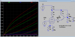
How to design BestPentode or other stage here for sharing. This plot looks more ultra-linear to me. Plug in the components and plot the curve, loadline etc, then use it in sch. Repeat until satisfied. Reduce R4 value will change the mode UL to triode gradually.
Attachments
Last edited:

Oh wow! I'm criticizing my own circuit! Well, I've learned something since I posted that a couple of years ago...
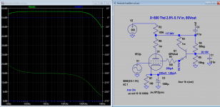
After building a similar 12AX7 phono preamp with a passively filtered power supply (no regulation), I found that the first stage 12AX7 is -extremely- sensitive to power supply impedance down around 1Hz (yes, one cycle per second). I was using something like 4.7k ohms and 33uF, which theoretically should be low enough, but there were weird rumbles happening down low from subsonic oscillations ("motorboating"). I wrote about it on this forum, and one kind person pointed out that the decoupling (dropping) resistor feeding the B+ to the first stage in a phono preamp needs to be relatively large in order to avoid these oscillations. He recommended at least 15% of the value of the first stage triode's plate load resistor. 15% of 150k is 22.5k, so there you go. I found that I needed 43k in the particular circuit I ended up building, since a 33uF electrolytic cap was already in the PCB (and it fit snugly too). Upping the decoupling resistor to 43k cured the motorboating.
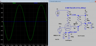
If you like that first circuit, here's an updated version that fixes those problems. I modeled it with a +320VDC B+ supply with 100mV of ripple riding on it. The output waveform shows no trace of ripple, so the power supply decoupling shown should work to filter out ripple and have low enough impedance not to oscillate at subsonic frequencies. For what it's worth, it's attached (the schematic on the left).
I'm also including a schematic of the RIAA preamp I'm listening to now. It's nothing special but I think it would be a good novice build, because it uses a passive power supply and tubes you can buy at Guitar Center. It was designed around 12AX7s, but I found that the roughly 200pF input capacitance is too much for my Audio Technica AT-VM95E cartridge, which has a recommended loading of not more than 250pF total (200pF 12AX7 Cin + 110pF tonearm cable + 30pF internal tonearm wiring = 340pF). So I put in a 12AT7 and I'll live with the reduced gain. The highs definitely sound more relaxed now, so I'm happy enough to listen to it. I am working on something better, though...
I forgot to mention that my current RIAA preamp was built using a pair of Merlinb's Compact Phono PCBs. Merlin's PCBs are good -- they're well thought out, they're well made, and they're not expensive. If you can scrounge up some 12AY7 or 6072, that would make a nice phono stage if you don't need gain of > 40dB. 12AY7 was often used in microphone preamps, so was designed for low noise. It also features much lower input C than 12AX7, so will play nicer with moving magnet cartridges. Or use a 12AT7 like I ended up doing. It distorts more, and doesn't have quite as low input C, but it can be made to work pretty well. The MOSFET source follower output frees you from worries about loading by cable runs or low impedance amplifier inputs.
The Valve Wizard
--
Building. Hope no problems.
If necessary, may I need Mr.Rongon's help?
Thanks./

Which point to lift up +70V?Absolutely!
Don't forget to lift the heater supply up about +70V. The 12AT7 has its cathode almost 160V above ground, so the heater supply should be lifted to compensate for that.
I can't tell from your photo how you did the heater supply for the 12AX7s and the 12AT7. Can you post a schematic of what you did?
Which point to lift up +70V?
Read here - https://www.valvewizard.co.uk/heater.html - under 'Heater Elevation'.
Attachments
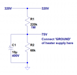
Heater supply for the all tubes: 6.3volI can't tell from your photo how you did the heater supply for the 12AX7s and the 12AT7. Can you post a schematic of what you did?
Best Pentode is just a cascode with triode on the bottom and transistor up top.The BestPentode is beyond me right now, but perhaps after more reading and thinking I'll come to an understanding. It may take some time.
What is the DC voltage at B+ ?
Looking at the schematic below, you will want to choose the values of R1 and R2 so that the DC voltage at the 'top' of R2, with the 10uF cap in parallel, is +70V.
That will 'lift' the heater supply on top of the +70V point at the junction of R1 and R2.
Last edited:
B+ = 296V. My system is 71 vol.Absolutely!
Don't forget to lift the heater supply up about +70V. The 12AT7 has its cathode almost 160V above ground, so the heater supply should be lifted to compensate for that.
I've never used this method before. What;'s purpose of LIFT heater up?
- Home
- Amplifiers
- Tubes / Valves
- Build Phono Preamp