Merlin used to sell a pcb for a similar design. The description can be found at this page The Valve Wizard 🙂
Thank you.
I don't see anything wrong with it since the input is from a MM cartridge in the range of 2-5mV so it's not likely to overload the input.
As I understand how these things work, overloading the input is not the point.
The point is grid current from contact potential, due to the extremely low grid bias (-0.44V).
Granted a 47k ohm grid leak resistor (the phono preamp input load resistor) will mitigate grid current somewhat. However, the general consensus seems to be that you want the grid bias on a 12AX7 to be at least -1V, and preferably more like -1.2 or more negative.
Merlinb said:rongon said:In a simple 12AX7 input gain stage such as this, is a Vg-k below 0.5V to be avoided at all costs?
In general, yes. However, you do get some second harmonic cancellation from the opposing curves of the grid current and tube non linearity, so a case could be argued for Broskie's choice of biasing. Nevertheless, I makes me uncomfortable; I would recommend adjust on test.
https://www.diyaudio.com/forums/tub...e-voltage-grid-current-12ax7.html#post4774653
DF96 said:Somewhere I have a copy of a paper published in the 1950s which suggests running the 12AX7/ECC83 in the region where grid current distortion opposes the normal anode distortion. It shows curves of second-harmonics being significantly reduced. Hooray!
What it also shows, but not commented upon as it was not realised back then how important it was, is the higher order distortions shooting up at the point where second reduces. This is exactly what you would expect to happen, as grid current produces a smoothish clipping on positive peaks. This is mainly second, but it has lots of higher orders too.
Unless you have a very low source impedance or very low signal amplitude (phono might qualify for the latter) I would keep the grid at least -1.0V wirh respect to the cathode. This means that the window of bias for the 12AX7 is quite narrow.
https://www.diyaudio.com/forums/tub...e-voltage-grid-current-12ax7.html#post4774662
...and so on.
Here's a circuit that uses two cathode followers in series at the output with second half of the split RIAA network in between.
96mA per channel of plate current for a phono preamp. Well, that would require a power transformer capable of delivering 200mA plate current for a stereo version, which is about the same as would be required for a stereo PP EL84 power amp. Seems a bit excessive, but I get your point. Yes, it's possible. But is it advisable?
--
Hi Chris
I could dispense with C1, but then wouldn't there be some DC on the RIAA network? Would that DC voltage carry some signal from the cathode of U1 that could interact with the filter in ways we don't want?
I have some 7.2uF metalized polypropylene capacitors I could put there. That would put the zero at 0.325Hz. That should be low enough not to interact in adverse ways at subsonic frequencies, no?
Or are you more concerned with the load 68k presents to the U2 6SN7 plate (rp = 10k or thereabouts)?
Perhaps 12AT7 would be a better compromise than 12AX7? I was thinking so because of the 12AT7's higher gm, lower rp, but still mu of 50 or so. It should be OK run with Ip of about 1.5mA to 2mA. I've attached a schematic to show what that might look like...
However, this is just a quick thought experiment. I'd use something like a 6DJ8 for the first two stages, or even a 6GK5 coupled to a 6N6P or 5687 (lots of plate current, mu of 16 to 20). Then perhaps make the RIAA network a lower impedance version (lower resistor/higher capacitor values). Or is it just as well to keep it as is, with 30k+1.8k for R8+R22, and adjust the value of R18+R23 as needed?
Understood, thanks. R17 is sort of a cathode 'stopper' resistor, so it needs to be very close to the cathode pin, like a grid stopper resistor would be to its grid pin.
--
If you're asking me to nitpick, I'd start with C1. It complicates your calculations some to not have C1, but that extra subsonic zero is a liability in a phono stage, whose input already contains large amounts of subsonic garbage from record irregularities emphasized by the cartridge compliance x tonearm effective moving mass fundamental resonance.
I could dispense with C1, but then wouldn't there be some DC on the RIAA network? Would that DC voltage carry some signal from the cathode of U1 that could interact with the filter in ways we don't want?
I have some 7.2uF metalized polypropylene capacitors I could put there. That would put the zero at 0.325Hz. That should be low enough not to interact in adverse ways at subsonic frequencies, no?
Or are you more concerned with the load 68k presents to the U2 6SN7 plate (rp = 10k or thereabouts)?
Because your RIAA eq is such high impedance (minimum 200K Ohm including R7) R16 has quite a lot of latitude, but more is still more better. Something like a 12AX7 for the first stage would scale both R4 and R16 up by maybe doubled? and reduce issues of excess (1/f) noise and (likely) microphonics.
Perhaps 12AT7 would be a better compromise than 12AX7? I was thinking so because of the 12AT7's higher gm, lower rp, but still mu of 50 or so. It should be OK run with Ip of about 1.5mA to 2mA. I've attached a schematic to show what that might look like...
However, this is just a quick thought experiment. I'd use something like a 6DJ8 for the first two stages, or even a 6GK5 coupled to a 6N6P or 5687 (lots of plate current, mu of 16 to 20). Then perhaps make the RIAA network a lower impedance version (lower resistor/higher capacitor values). Or is it just as well to keep it as is, with 30k+1.8k for R8+R22, and adjust the value of R18+R23 as needed?
R17 should be mounted very close to the socket pin, to help minimize parasitics with its capacitive load. All looks good to me.
Understood, thanks. R17 is sort of a cathode 'stopper' resistor, so it needs to be very close to the cathode pin, like a grid stopper resistor would be to its grid pin.
--
Attachments

Last edited:
Second try --
[12AT7 - 12AT7] -> RIAA -> [6SN7 -> 6SN7-CF]
|-----NFB------|
The second 12AT7 (U2) has Ip of 3.5mA. Is that enough plate current to drive the NFB loop and the RIAA EQ?
It's so easy to get the EQ flat with this topology...
[12AT7 - 12AT7] -> RIAA -> [6SN7 -> 6SN7-CF]
|-----NFB------|
The second 12AT7 (U2) has Ip of 3.5mA. Is that enough plate current to drive the NFB loop and the RIAA EQ?
It's so easy to get the EQ flat with this topology...
Attachments
Last edited:
DC voltage ends at C3, so not understanding your concerns with RIAA interaction? My concerns with C1 are partly technical (see Shure's noise data here: Stereo Lab - Maximum recorded velocities on gramophone records ) and partly aesthetic (if a circuit element degrades performance, could be removed, then should be removed, yada yada).
It's trickier to design, with very significant (1.3mA as shown!) DC current added to cathode current through R4. A little easier with a 0.5mA cathode current valve like 12AX7, 6SL7, etc. But you could offset the pain some by direct coupling U1 to U2. Then the heavy DC feedback could be a stabilizing force for good. Might be tough to squeeze into a 310VDC B+ supply though.
Edit: this doesn't apply to your circuit of post #64.
Please don't let my prejudices deter you from your excellent design work. I would do some things differently, but I'm old and largely set in my ways.
All the best fortune,
Chris
Last edited:
Those last two simulations (posts 63 and 64) were basically for proving the concept to myself. I think I'm sold. I've been thinking about how to refine the idea.
It seems that I want to have less current in the feedback loop rather than more, correct? Do I want >7mA of plate current in U2 to drive the RIAA network and the feedback loop, or is the roughly 3.5mA Ip for U2 as shown in post 64 a better way to go? I only understand negative feedback mechanisms on a fairly superficial level. My assumption is that more plate current through U2 will allow that stage to drive its load with greater ease, and not run into slew limiting or other nasties.
I could use less NFB around U1 and U2, allowing for more gain, and use less gain for U3. Perhaps use a half a 5687 or 6N6P, run it at Ip = 15mA with a 10k plate load resistor, with A = 12 or so. That should have a low enough output impedance of about 2k (maybe less), and hopefully still low enough THD.
I like the idea of having a high gm triode as the input tube, but those all require more plate current than 12AT7. I was thinking of something like a 5842 or 6GK5, possibly into a half a 5687 or 6N6P.
Now that we know what the topology would look like, I can imagine all sorts of variations on the basic theme.
EDIT TO ADD:
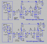
One of the cool things about this topology is that the feedback pair will have very low THD, so the third stage is where all the distortion will happen. Keep that stage clean and the whole preamp will be very clean. LTspice predicts the version in post 64 will have THD of about 0.02% with 5mV RMS in (1kHz). Gain looks to be about 41dB in to out at 1kHz.
It seems that I want to have less current in the feedback loop rather than more, correct? Do I want >7mA of plate current in U2 to drive the RIAA network and the feedback loop, or is the roughly 3.5mA Ip for U2 as shown in post 64 a better way to go? I only understand negative feedback mechanisms on a fairly superficial level. My assumption is that more plate current through U2 will allow that stage to drive its load with greater ease, and not run into slew limiting or other nasties.
I could use less NFB around U1 and U2, allowing for more gain, and use less gain for U3. Perhaps use a half a 5687 or 6N6P, run it at Ip = 15mA with a 10k plate load resistor, with A = 12 or so. That should have a low enough output impedance of about 2k (maybe less), and hopefully still low enough THD.
I like the idea of having a high gm triode as the input tube, but those all require more plate current than 12AT7. I was thinking of something like a 5842 or 6GK5, possibly into a half a 5687 or 6N6P.
Now that we know what the topology would look like, I can imagine all sorts of variations on the basic theme.
EDIT TO ADD:
One of the cool things about this topology is that the feedback pair will have very low THD, so the third stage is where all the distortion will happen. Keep that stage clean and the whole preamp will be very clean. LTspice predicts the version in post 64 will have THD of about 0.02% with 5mV RMS in (1kHz). Gain looks to be about 41dB in to out at 1kHz.
Last edited:
Thinking about it some more... Thinking about how to make the 3rd stage super-clean and with low output impedance, I hit upon the idea of using a 6SN7 (a very clean triode) in a mu follower with a depletion mode MOSFET as its plate load, and take the output from the source of the MOSFET (a quasi-source follower).
Yes, it will have low impedance, but no it will not be a super-strong line driver. But that's OK. It's a phono preamp. It will drive a short length of cable into a selector switch and volume control, or into a line preamp. It won't be driving a power tube or anything like that. Right?
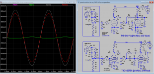
In LTspice, the attached circuit yields 45dB gain at 1kHz, and the THD with 5mV RMS into a 47k ohm load is minuscule, just 0.0055%. THD at that level goes up to 0.01% into a 10k ohm load.
This confirms my suspicion that the U1-U2 feedback pair is very, very clean, and all the THD will come from that third stage.
I don't know. This looks really good to me. Maybe it needs a follower on the output.
Any nits to pick? I'm all ears...
Yes, it will have low impedance, but no it will not be a super-strong line driver. But that's OK. It's a phono preamp. It will drive a short length of cable into a selector switch and volume control, or into a line preamp. It won't be driving a power tube or anything like that. Right?
In LTspice, the attached circuit yields 45dB gain at 1kHz, and the THD with 5mV RMS into a 47k ohm load is minuscule, just 0.0055%. THD at that level goes up to 0.01% into a 10k ohm load.
This confirms my suspicion that the U1-U2 feedback pair is very, very clean, and all the THD will come from that third stage.
I don't know. This looks really good to me. Maybe it needs a follower on the output.
Any nits to pick? I'm all ears...
Attachments
The old rule of thumb for triode loading is that if your load's impedance is 4 or 5 times larger than the plate load resistor, you're fine and don't need to worry too much about it. This comes from looking at typical characteristic curves for typical audio triodes - the less the load line is skewed clockwise, the better the linearity, but a smallish rotation isn't a problem.
Slew limiting is an idea from opamps, a measure of performance under complete clipping. Drive the input with a very big zero rise time edge and count how long it takes the output to get up to some percentage of max. This tests the same mechanism that causes distortion to increase as frequency increases ("filling up all the little capacitors" as 1Audio put it on his Burning Amp video, very very highly recommended) but is not exactly the same thing. I'd suggest that a better view would be the simpler one of effects on the loadline, conceptually correct, and more direct. Anyway, in your circuit, you're driving mostly resistors.
The third stage works at fairly similar gain, signal and impedance levels as the first pair, so could be a similar construction if you wanted to for some reason.
It (finally) occurs to me that feedback could be taken from both before and after C3, simplifying the juggling act. Also you can lose R7.
All good fortune,
Chris
Last edited:
It (finally) occurs to me that feedback could be taken from both before and after C3, simplifying the juggling act.
Before C3? That would require another capacitor, like the C1 I used in post 63. Taking feedback from both before and after C3 would put the two in parallel? I guess I'm lost.
I thought of something else... What if the first stage was an 'anode follower' using shunt feedback from plate to grid, with a 47k ohm series resistor to the virtual ground point? Wouldn't that make the input resistance 47k ohms (or very close to it)?
One could use a pentode for the first stage, with shunt feedback plate to grid, forcing 47k ohms input resistance and doing a lot with one tube. Perhaps a 6J9P with 8mA of plate current and a 10k ohm plate load resistor, with its gain reduced from 80 to about 40?
Also you can lose R7.
You're right! It actually lightens the load a little on U2, so gain goes up a tiny bit.
I guess R16 and R4 are the path to ground for C3.
Thanks. I didn't see that at all.
Last edited:
Just thinking that you may or may not want *some* DC current coming down the feedback path, as part of the biasing/feedback juggling act. Feedback from both ends of C3 would complicate the calculations for your low frequency high pass pole, but you've got one a 'em computer thingys to do it. And I'm still thinking in 12AX7 terms, because 12AX7.
Noise (Johnson/Nyquist/thermal) becomes an issue putting the 47K load in series with signal. Also, frequency response will vary with the sum of cartridge source impedance plus 47K Ohms. I love anode followers, but they require a defined resistive source impedance. edit: unless they're a Baxandall tone control!
Those little hot pants Russian pentodes would make excellent phono stages. They have very low excess noise (a potentially major issue with RIAA playback curves superimposed) and are cheap and cheerful. Read Frank Blohbaum(mit der Umlaut)'s article in the 0th issue of Linear Audio addressing partition noise. Contains noise tests of several very interesting valves.
I do not fear the Pentode,
Chris
Last edited:
Let me toss out a pair of options, based on your openness to new ideas: first is a 6J9P in BestPentode configuration, cathode resistor degenerated to a flat gain of 30-couple dB, then a total loss RIAA with 20dB midband loss, then another 6J9P same as the first.
Second option has the same first stage, but the lossy RIAA network has only the 50Hz pole and 500Hz zero. Second stage is a 6J9P as before, but with the 75uS pole in anode follower feedback. Probably don't want cathode resistor degeneration for that, but maybe. Wouldn't effect the pole's location either way.
All good fortune,
Chris
Borbely RIAA Preamp With Tubes - A Project Remembered and Revisited | audioXpress
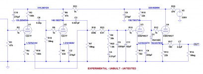
Has anyone built this? It's passive and active combined EQ. Thd is good esp. with 6N1P.
5842 THD 0.021% @1m V(in), 0.52 V(out)
6N1P THD 0.0075% @1mV(in), 0.46V(out)
Has anyone built this? It's passive and active combined EQ. Thd is good esp. with 6N1P.
5842 THD 0.021% @1m V(in), 0.52 V(out)
6N1P THD 0.0075% @1mV(in), 0.46V(out)
Attachments
Last edited:
@Koonw
Thanks, I had just recently looked at that Borbely/Tritschler circuit. I forget who posted it...
The one criticism I have is that it does not address the problem of input capacitance. 5842 has moderately high mu (but nice high gm), but quite high Cin. That' a deal killer for me, I'm afraid. I'm finding that with the cartridges I use, the input tube's Cin has to be kept below 100pF.
I'm finding that you can get really super-low THD by keeping the gain down (why the 6N1P version has lower THD than the 5842 version). That's another problem for me, because I really do want a total preamp gain of 45dB, so that subjectively my records match the playback level I get from my DAC.
Otherwise, yes, that does look like a good circuit.
@Chris
Thanks, I do try to keep an open mind. I'm seeing that there is no holy grail 'best' design. Everything is a bunch of compromises based on design goals. My goals for an RIAA preamp are low Cin, 45dB gain, using vacuum tubes. Using only triodes and without NFB would be nice, but those are not essentials for me. Good PSRR would be a very good thing. It would be nice if the end result sounds pleasing too.
I need to read up on BestPentode operation. I haven't been paying any attention to that. Where's a recommendable place to learn about that?
--
Last edited:
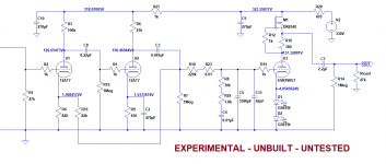
How about adding a jfet low gain stage, that boost the gain and reduced Miller effect like this? (that is for MC)
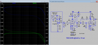
https://i81.photobucket.com/albums/j207/merlinblencowe/zero_bias_THD_zps149c3fc1.png
https://i81.photobucket.com/albums/j207/merlinblencowe/zero_bias_THD_zps149c3fc1.png
Re: BestPentode
I was thinking a 6F12P would be a good candidate, since it has a high gm RF pentode and frame grid high mu triode in one 9pin mini bottle. I did a search and found bondini's circuit using BestPentode > passive RIAA > Triode. kevinkr recommended adding a MOSFET source follower on the output. This could be re-jiggered to put half the EQ in a feedback loop around the output triode (anode follower-style).
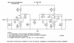
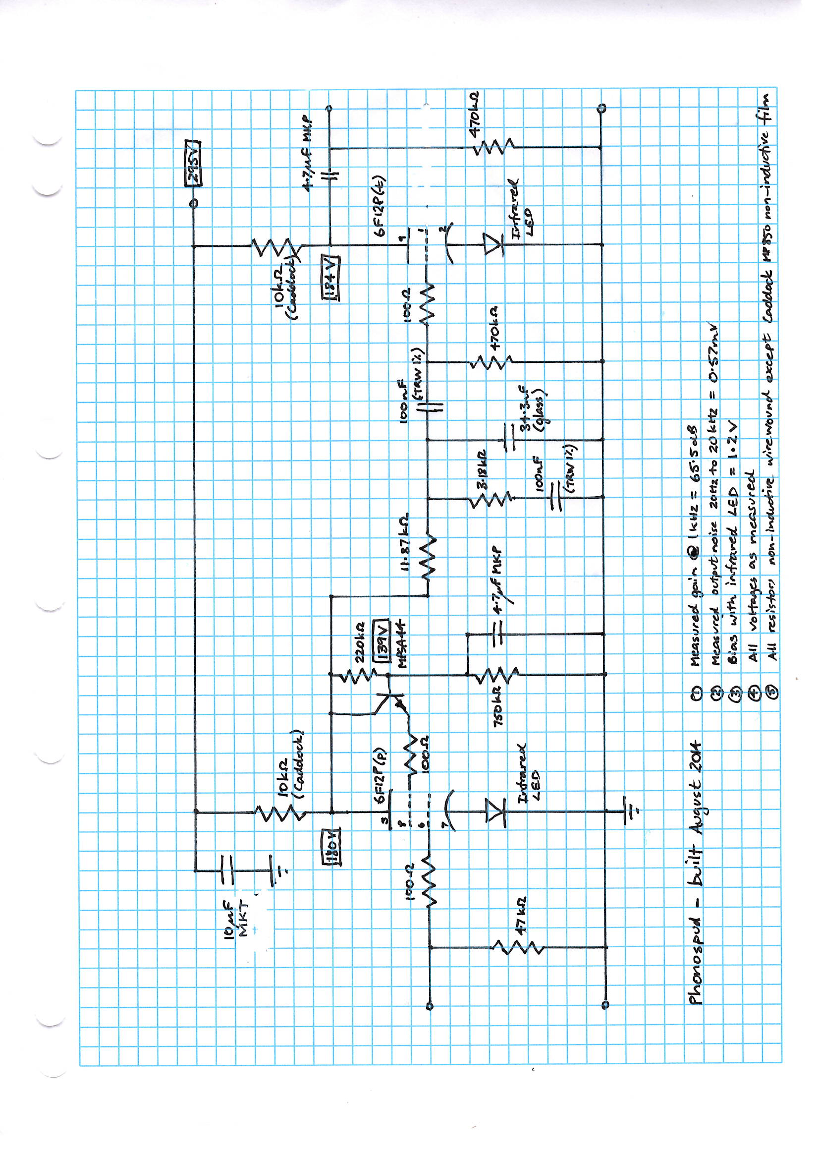
Phonospud – sandy Muscovite Micro with a pentode first stage
I need to read more about the BestPentode. I don't understand it well enough to design my own, yet...
I was thinking a 6F12P would be a good candidate, since it has a high gm RF pentode and frame grid high mu triode in one 9pin mini bottle. I did a search and found bondini's circuit using BestPentode > passive RIAA > Triode. kevinkr recommended adding a MOSFET source follower on the output. This could be re-jiggered to put half the EQ in a feedback loop around the output triode (anode follower-style).
Phonospud – sandy Muscovite Micro with a pentode first stage
I need to read more about the BestPentode. I don't understand it well enough to design my own, yet...
How about adding a jfet low gain stage, that boost the gain and reduced Miller effect like this? (that is for MC)
https://i81.photobucket.com/albums/j207/merlinblencowe/zero_bias_THD_zps149c3fc1.png
Two reasons I don't like it:
1) It adds yet another stage, and
2) The THD is really high.
But thanks.
I post this before, but no sure if the 6F12p model is accurate or not, which model do you have?
NEW D3a equivalent on market?
NEW D3a equivalent on market?
I thinking to remodel it with passive and active EQ, then no extra buffer is required as active portion has feedback to lower the output Z, right? Right now triode has 10k anode load, which can drive a lot of amps include solid state, but the gain needs to be reduced either by feedback or degeneration or just by a pot. The gain is X6 RCA riaa or 6V/1V.
Last edited:
- Home
- Amplifiers
- Tubes / Valves
- Build Phono Preamp