As I understand it, Koonw found that putting a cathode follower (or source follower) directly after the RIAA EQ network lightens the load on the input stage. The follower will have very low input capacitance, that's for sure -- especially compared to a fully bypassed 12AX7 common cathode stage (roughly 200pF).
I have never seen that configuration before. Certainly there are examples of a cathode follower placed after the input stage (Marantz 7C, Broskie GlassWare Tetra Sans PS, Waltube Junior), which will drive the RIAA EQ network more easily.
How many followers can be put in a row? What is the circuit was laid out as
Input stage =
Common Cathode DC coupled to Source Follower
Then comes the RIAA EQ DC coupled to Source Follower
Then comes another Common Cathode DC couple to Source Follower
2 gain stages and 3 followers/buffers.
How would that work?
https://www.diyaudio.com/forums/att...-build-phono-preamp-phono-6n1-6n1-6n2-6n1-png
There are at least 2 (maybe White) buffer/follower in this schematic. Had he chooen RCA type RIAA EQ that we're using, another buffer would be required. But as he uses a low impedance type EQ response is least affected by Miller capacitance. This is something that might cause misunderstand between the 2 EQ. Whether kodabmx awares of that I don't know, but he just jump at me when I posted my sch.
There are at least 2 (maybe White) buffer/follower in this schematic. Had he chooen RCA type RIAA EQ that we're using, another buffer would be required. But as he uses a low impedance type EQ response is least affected by Miller capacitance. This is something that might cause misunderstand between the 2 EQ. Whether kodabmx awares of that I don't know, but he just jump at me when I posted my sch.
Last edited:
TDHien59 said:I am considering this. Is it belong to Rongon?
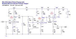
Yes, but I have not built that circuit. In simulation it looks like it will work well. Low THD, accurate RIAA curve. I measured the frequency response with a signal generator, KAB inverse RIAA box, and oscilloscope. Unfortunately, there was interference in the displayed waveform, which made it impossible to get really precise amplitude readings. All I can say is that visually the response looks flat, ever so slightly attenuated above 10kHz, because I changed the values of C5 slightly to suit my particular system. The values shown in the schematic are correct for flattest response.
This 12AX7-based circuit will have high input capacitance (about 200pF) which means it will cause a peak (resonance) around 8kHz to 10kHz if you use it with a typical moving magnet cartridge like Nagaoka, Audio Technica, even most Shure cartridges. That's a problem with all 12AX7 preamps.
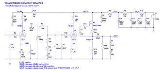
Attached is the schematic for a simple circuit I have built and am running now. I built it in one of Merlinb's Compact RIAA pcbs, which are available from his website. I'm using it with 12AT7 (ECC81) instead of 12AX7 for lower input capacitance (and lower gain, but slightly higher THD). This circuit uses a MOSFET source follower on the output, not a tube cathode follower.
The advantage of that circuit is that you can use a 12AT7 instead of the 12AX7 and it actually works quite well, with input C down around 100pF. That seems to work much better with my Audio Technica MM cartridge. It also should work very well with a 12AY7 (6072), but those are not so easy to find.
The MOSFET source follower does not require a heater supply, so there's no need to lift the heater supply far above ground. I'd lifted the heater supply to +30VDC, because that is supposed to reduce noise, but it doesn't really have to be lifted at all.
That MOSFET could be replaced with a cathode follower using a tube like a 12AU7 (ECC82), 5965 or 12AV7, but then you'd need to increase the current capability of the DC heater supply and you'd be required to lift the heater supply 'ground' to about +40VDC.
I used a regulated DC power supply for the tube heaters (not shown), using a 12.6VAC 1.2A transformer (15VA) and a LD1084 voltage regulator IC. I used a Pete Millett DC heater supply PCB for that.
For the B+ supply, I used one of Merlinb's basic DC B+ supply PCBs, and added a resistor-capacitor decoupling network (R3 and C14).
TDHien59 said:Which one can replace Diode 1N4148C?
That should be "1N4148", which is the same as 1N914 (signal diode).
You can use a plain neon bulb instead, but not the kind designed to be used as an AC mains indicator lamp, because those have a series resistor to limit current, which you do not want in this situation.
You could also use pretty much any rectifier diode like 1N4004 or UF4004. The purpose of that part is to keep the cathode from getting too high in voltage from the heater during start-up, which can stress the heater-cathode insulation and cause the cathode follower tube to get too noisy.
EDIT TO ADD: I think Waltube's circuit will be better, but it's slightly more complicated. However, he has a full set of PCBs available, so that might actually be simpler in the end.
kodabmx's circuit should work well too, but like you said, it does use a lot more tubes.
Attachments
Last edited:
How about running that sim using 240R instead of 560R? Does the higher current lower the THD?
I'm sorry, I'm not sure which sim you're referring to. The 6N1P half-mu? The 6N1P mu-follower? The 6N1P bypassed common cathode stage?
LATER...
I simulated the 6N1P half-mu stage with
B+ = 250V
Vp = 125V
Vg = -1V
Ip = 4.2mA
Rk = 240 ohms
The gain went up slightly to 20.5 (it was 19.9 with Rk = 560)
THD went down to 0.035%
HOWEVER...
The grid bias is only -1V. If the 6N1P starts drawing grid current, it will distort the signal from the previous (driving) stage. So while the triode might be generating less THD, the previous stage may distort pretty badly, unless it can drive a relatively low (and possibly varying) impedance.
I don't know if that will be a problem in real life, but theoretically you want to keep the triode biased well away from its grid current region. Some 6N1P tubes might draw grid current at that bias point, while others may not. Now we're getting into selecting tubes for lowest grid current, which I think is an unnecessary complication. But if you have a large stash of those tubes and you're willing to select good ones, then this is probably not an issue.
MORE...
If I increase the B+ to 330V...
Vp = 165V
Vg = -1.5V
Ip = 6.3mA
Rk = 240 ohms
A = 21
THD = 0.034%
I'm sure Vg = -1.5V is well clear of grid current.
Looks to me like 6N1P is a tube that likes a fairly high B+, like 6SN7 (6N8S) or 12AU7, rather than being happy with a +200V B+ like 6DJ8, ECC88, 6N23P is.
--
Last edited:
The grid bias of -1V isn't an issue with 6N1P in my experience, according to these curve traces, and the face that the real circuit uses more current at that voltage point. The entire stereo board typically draws 50mA
I also have boards in stock for the schematic as drawn, and one that changes the first two 6N1P to 6N3P - still great sound but the tubes are cheaper and use half the heater power. I'm building a preamp using one of them now.
@Koonw
Sorry, I didn't mean to jump on anyone about anything.
Yes, there are two active buffers in the half-mu design. One driving the RIAA EQ, the other driving the load.
If more current is needed, the 6N1P buffer in the last position could use 6N6P instead.
Another trick I use is to cycle the power to the phono stage so it only powers up when I'm listening to records (the selector switch grounds a relay to switch power). The tubes last for a long time that way 🙂
Attachments

FWIW, I've also built this one - it was my first.
Nice sound but it could pick up radio with certain tubes (I could hear CHFI 99.9 FM with no tuner).
I thought it was cool because it splits the RIAA EQ into two sections.
Bob's Vacuum Tube Phono Preamp
Nice sound but it could pick up radio with certain tubes (I could hear CHFI 99.9 FM with no tuner).
I thought it was cool because it splits the RIAA EQ into two sections.
Bob's Vacuum Tube Phono Preamp
Attachments

Last edited:
to rongon
"I think Waltube's circuit will be better, but it's slightly more complicated. However, he has a full set of PCBs available, so that might actually be simpler in the end."
Please can you tell me where the Junior is more complicated?
Agree with the help of pcb
Walter
"I think Waltube's circuit will be better, but it's slightly more complicated. However, he has a full set of PCBs available, so that might actually be simpler in the end."
Please can you tell me where the Junior is more complicated?
Agree with the help of pcb
Walter
to rongon
"I think Waltube's circuit will be better, but it's slightly more complicated. However, he has a full set of PCBs available, so that might actually be simpler in the end."
Please can you tell me where the Junior is more complicated?
Walter
More tubes, more parts. Only *slightly* more complicated. Also, more complex power supply (solid state regulated vs. passive RC decoupling networks).
However, the slight additional complications improve the performance. Essentially, the additional complications are the cathode follower after the first stage triode and the SS regulated psu. Both additions are worth the extra parts, in my opinion.
Have you tried the Junior with ECC81 in the input stage? Does it make enough gain, not distort too much more? (ECC81 is generally less linear than ECC83, but it also has less input C, so is *sometimes* worth using, but not in every case.)
Last edited:
All the parts involved on this circuit are well dimensione to get the best results possible with a great possibility to use different tubes
Also the ss power is the right way to have a very good s/n
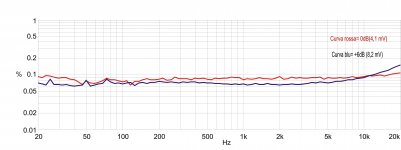
On curves I posted (post 31) there is also the one with ECC81.
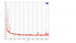
I can add the FFT and Thd vs freq.
All test lab and not simulation
Walter
Also the ss power is the right way to have a very good s/n
On curves I posted (post 31) there is also the one with ECC81.
I can add the FFT and Thd vs freq.
All test lab and not simulation
Walter
Attachments
This 12AX7-based circuit will have high input capacitance (about 200pF) That's a problem with all 12AX7 preamps.
While this is true for circuits without feedback to the first stage cathode, very popular now, it's not really carved in stone. Input capacitance is reduced by the ratio of gain reduction from feedback.
Significant feedback to the first cathode could be done in a three stage amplifier while keeping the popular total loss RIAA eq between stages if desired. An example would be a first quiet stage of high gain, a lower gain higher power output second stage, to drive the lossy eq, and flat feedback from second stage anode to first stage cathode. Third stage would be flat make up gain and buffering to the cold cruel world outside.
Of course, Golden Era designs with RIAA eq in a feedback loop to first cathode do this too, and modern opamp copies.
Your championing of the importance of controlling cartridge loading is very important and significant. Otherwise folks tend to drift down familiar and fashionable paths, and wonder why they're not happy.
All good fortune,
Chris
Last edited:
While this is true for circuits without feedback to the first stage cathode, very popular now, it's not really carved in stone. Input capacitance is reduced by the ratio of gain reduction from feedback.
Yes, quite true.
Significant feedback to the first cathode could be done in a three stage amplifier while keeping the popular total loss RIAA eq between stages if desired. An example would be a first quiet stage of high gain, a lower gain higher power output second stage, to drive the lossy eq, and flat feedback from second stage anode to first stage cathode. Third stage would be flat make up gain and buffering to the cold cruel world outside.
It took me a while to catch on to what you're saying here, but it finally sank in. Yes, I see what you mean. That would be an interesting topology to explore.
Of course, Golden Era designs with RIAA eq in a feedback loop to first cathode do this too, and modern opamp copies.
That's what I saw in your post that reminded me of Morgan Jones' discussion of the Marantz 7C, etc.
Your championing of the importance of controlling cartridge loading is very important and significant. Otherwise folks tend to drift down familiar and fashionable paths, and wonder why they're not happy.
Guilty as charged. Going down that road I've found out why the otherwise really good looking 12AX7 just doesn't float my boat. That 8kHz spike in the response from the cartridge is not my cup of tea. There are quite a few ways to approach that problem, like using one of those high mu frame grid RF triodes with very low Cga driving a passive EQ.
I'll have to play around with that idea of having cascaded triodes with NFB from V2 plate to V1 cathode, then a passive RIAA, then a final gain stage with low Zout to drive whatever the external load will be. The NFB will increase PSRR, lower noise, all sorts of good stuff could happen. Thanks for the idea. Very interesting. I'm a little embarrassed about how long it took me to catch on to what you'd written!
--
Last edited:
Thinking about that idea...
The one criticism I can think of right away is that the 2nd stage tube will have to drive both the NFB loop *and* the passive RIAA EQ. I guess that's why you suggested a power tube for that 2nd stage, correct?
Perhaps use something like a 6J9P-triode for the input stage (V1), DC-coupled to half a 6N6P with Ip = 15mA (V2). The combination of those two stages would make about 35 x 15 = 525X gain, which could be reduced to roughly 150X gain by applying 10dB of NFB (V2 plate to V1 cathode).
Reducing the gain of the V1 triode by 3.5X would decrease its Cin by about the same, correct? Being that the Cin of a 6J9P-triode is about 150pF, reducing that by 3.5X would bring Cin down to 42.9pF. That's about as low as you'll see from any frame grid RF triode, but with 3X the gain (and lower noise and better PSRR).
150X is still a lot of gain (43.5dB). The V2 (6N6P) plate couples to the passive RIAA, losing 20dB, so now we're back at 23.5dB gain (15X). Assuming the input signal was the nominal 7.07mV peak (5mV RMS), 7 x 15 = 105mV peak (74mV RMS) at the grid of the 3rd stage (V3).
An output stage with only 10X gain (20dB) would get the entire preamp to 43.5dB gain, which is certainly enough. The output stage could be something really simple, like the other half of the 6N6P.
And Bob's yer uncle!
Last edited:
Edit: I'm several posts behind,
You've raised several good points. To respond to the issue of RIAA eq: a complete correction for RIAA pre-emphasis needs the low frequency end to get up to 17dB above midband at 50Hz and for the high frequency end to continue falling for some ways above 15kHz. Both are tricky with simple finite-gain non-inverting amplifiers. The second part is an excellent argument for the modern lossy eq paradigm. The first can be done, but requires everything to work just right because closed-loop gain needs to run up right next to open-loop gain. Not robust in the modern view of things.
The original opamps were made with valves (if you ever find a 12AX7 labeled "GAP" you have a classic) but the concept hasn't changed. It works fine in monolythic semicom construction, and FET input modern opamps make fine phono stages, but maybe not a lot of fun. Does completely solve the problem of calculating the the low frequency stop though - just assume infinite gain - done.
"Since the level of NFB varies with frequency, and it's being fed to the cathode of the first triode gain stage, won't the Miller effect on that first triode also vary with frequency? The input capacitance would vary with frequency"
Yes. Although the result might be small compared to residual strays, this is true. It's linear, in the sense of not contributing harmonic distortions, because it's not level-dependent, but it's there. Cool spot.
The circuit I'd proposed recently doesn't have this issue, or the gain-stop issue of non-inverting circuits (because it's total loss eq) but same goals could be reached with the third stage as an anode follower with RIAA in its feedback network and the second stage (again!) optimized to deliver power. This issue of power delivery in the middle of the phono device seems to come up the more I look into this.
All good fortune, and much thanks,
Chris
Last edited:
Thinking about that idea...
The one criticism I can think of right away is that the 2nd stage tube will have to drive both the NFB loop *and* the passive RIAA EQ. I guess that's why you suggested a power tube for that 2nd stage, correct?
Perhaps use something like a 6J9P-triode for the input stage (V1), DC-coupled to half a 6N6P with Ip = 15mA (V2). The combination of those two stages would make about 35 x 15 = 525X gain, which could be reduced to roughly 150X gain by applying 10dB of NFB (V2 plate to V1 cathode).
Reducing the gain of the V1 triode by 3.5X would decrease its Cin by about the same, correct? Being that the Cin of a 6J9P-triode is about 150pF, reducing that by 3.5X would bring Cin down to 42.9pF. That's about as low as you'll see from any frame grid RF triode, but with 3X the gain (and lower noise and better PSRR).
150X is still a lot of gain (43.5dB). The V2 (6N6P) plate couples to the passive RIAA, losing 20dB, so now we're back at 23.5dB gain (15X). Assuming the input signal was the nominal 7.07mV peak (5mV RMS), 7 x 15 = 105mV peak (74mV RMS) at the grid of the 3rd stage (V3).
An output stage with only 10X gain (20dB) would get the entire preamp to 43.5dB gain, which is certainly enough. The output stage could be something really simple, like the other half of the 6N6P.
And Bob's yer uncle!
Hi Rongon!
Can you design this schematic using 6H1P, 6H2P repalces for 12AX7, 12AT7?
Where I live, tube 6H1P/6H2P are very low cost and available.
Thank you.
Attachments
Hi Rongon!
Can you design this schematic using 6H1P, 6H2P repalces for 12AX7, 12AT7?
Where I live, tube 6H1P/6H2P are very low cost and available.
Thank you.
Sure.
6N2P is pretty much the same thing as a 12AX7 (actually better!), but with a 6.3V heater instead of the 12.6V. So you could simply use the 6N2P instead of the 12AX7.
6N1P is a bit different from 12AT7, but since that's the cathode follower, 6N1P works well there too.
Of course both 6N2P and 6N1P require a 6.3V heater supply on their pins 4 and 5, which is different from how the 12AX7 and 12AT7 heaters would be connected.
I simulated the response of the same circuit using 6N2P and 6N1P and it came out pretty close to the same as with 12AX7 and 12AT7. Some minor tweaking of values might be necessary to achieve fully accurate RIAA equalization.
You might want to decrease the value of R5 to about 23.5k ohms, and increase the value of R4||R15 to total 274k ohms (instead of the 264k ohms in the 12AX7 circuit).
Put 68pF in parallel with C7 to make 3.368nF. That's because of the lower Cin of 6N2P compared to 12AX7 (which I rate as a very good thing).
R8 can be reduced to 10k ohms.
Everything else can stay the same.
Last edited:
I do want to point out that in the previous post's 6N2P-based circuit the first stage will sink a meager 0.7mA of plate current to drive the RIAA network. As Chris has pointed out, it looks like a healthy amount of power is required to really drive a passive RIAA network well. Any 12AX7, ECC83 or 6N2P common cathode stage will not do that, not even close. A cathode follower, emitter follower or source follower before the network would help, of course.
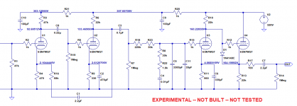
Thinking about what Chris wrote in the post before that, I decided to put the proposed topology to the test in a quick-and-dirty simulation. I used all 6SN7 tubes, because those are a known quantity.
The first two stages form a 'ring of two' feedback pair, with the input common cathode 6SN7 (V1) RC-coupled to a second common cathode 6SN7 (V2). V1 has no cathode bypass capacitor, while V2 is bypassed. Feedback is taken from the plate of V2 to the cathode of V1. Open loop gain would be about 300 (49.5dB), to which 11.5dB of NFB is applied. That brings the gain of the first two stages down to about 38dB.
Since 11.5dB NFB is applied to the input triode, its Miller capacitance should also be reduced by that much (3.75X). The Cin of a degenerated 6SN7 should be around 50pF, divided by 3.75 equals only 13.3pF!
V2 is biased to a healthy Ip = 7.9mA, which drives both the NFB loop and the RIAA network. Perhaps more power is needed here? I don't know.
The passive (lossy) RIAA EQ comes next, an all-in-one-go RC network. That has -20dB insertion loss. Gain after this is now 18dB.
The 3rd stage is a standard common cathode 6SN7 (V3) DC coupled to a 6SN7 cathode follower (V4). The combination of V3 and V4 provides gain of about 20X (10dB), so the total gain of the preamp is roughly 38dB. That's pretty standard for a phono preamp.
THD looks like it should be really low for a triode based preamp.
RIAA accuracy should be pretty good.
I'm sure this could be improved, but the circuit is straightforward and simple, and its simulation went together really easily.
What do you think, Chris? Any obvious improvements you can suggest?
--
EDIT TO ADD:
I thought of a potential issue with applying NFB to the input stage of an RIAA preamp.
The NFB reduces the signal appearing at the grid of the first stage. The signal is likely to be very small to begin with, likely 1mV to 5mV RMS most of the time. 10dB of NFB would reduce the signal level by about 3X, so a 1mV input signal looks like 330uV (0.33mV) on the grid. What impact would this have on noise? I would guess that the noise level at the input is reduced by the same feedback ratio as the wanted input signal, so it neither helps nor worsens SNR. Is that correct?
--
Attachments
Last edited:
It would be better to say that all of the input signal still appears across the amplifier's input, but feedback is applied in series with it (to the inverting input). It's not as obvious as an opamp, but works the same way for noise.
If you're asking me to nitpick, I'd start with C1. It complicates your calculations some to not have C1, but that extra subsonic zero is a liability in a phono stage, whose input already contains large amounts of subsonic garbage from record irregularities emphasized by the cartridge compliance x tonearm effective moving mass fundamental resonance.
Because your RIAA eq is such high impedance (minimum 200K Ohm including R7) R16 has quite a lot of latitude, but more is still more better. Something like a 12AX7 for the first stage would scale both R4 and R16 up by maybe doubled? and reduce issues of excess (1/f) noise and (likely) microphonics.
R17 should be mounted very close to the socket pin, to help minimize parasitics with its capacitive load. All looks good to me.
All good fortune,
Chris
There *may* be some advantage to letting U1 and U2 share a common B+ takeoff point. That way, signal perturbations of the B+ are guaranteed to always be negative feedback with no time delay. Figuring out if this holds true here makes my hair hurt, but a computer simulation might tell you something of interest. Naturally, you'd be looking at very low frequencies, but if the results don't appear on a frequency vs. magnitude run, it probably doesn't matter enough to worry about.
I might be tempted to cheat C8 down somewhat, or maybe just C3 instead. The last (IEC) suggested replay curve included a 20Hz pole. Even a 10Hz pole would usually be a good thing. There's a crap-ton of subsonics coming off records.
Always good fortune,
Chris
I might be tempted to cheat C8 down somewhat, or maybe just C3 instead. The last (IEC) suggested replay curve included a 20Hz pole. Even a 10Hz pole would usually be a good thing. There's a crap-ton of subsonics coming off records.
Always good fortune,
Chris
Can you design this schematic using 6H1P, 6H2P repalces for 12AX7, 12AT7?
Where I live, tube 6H1P/6H2P are very low cost and available.
Thank you.
Merlin used to sell a pcb for a similar design. The description can be found at this page The Valve Wizard 🙂
(The schematic below) has the 12AX7 tubes biased almost into grid current, with only -0.44V grid to cathode of the first stage 12AX7.

I don't see anything wrong with it since the input is from a MM cartridge in the range of 2-5mV so it's not likely to overload the input. The circuit above is John Broskie's remake of the RCA phono stage and how he describes it below.
*TCJ Remake of RCA Phono Stage
"In general, the original RCA phono stage isn't very good, as it isn't particularly flat or suitable for modern use. On the other hand, it does use passive equalization, which is cool; and it is very simple, which is why it is so popular. Here is my remake of the old design:
This tube phono preamp is flat from 20Hz to 20kHz within 0.1dB and the 12AT7-based Aikido cathode follower (ACF) stage greatly improves the PSRR and offers a low output impedance. The only difficult part of designing this phono stage was making sure that readily available RIAA EQ capacitors were used, which s why two 4.7nF capacitors were placed in parallel. The gain comes in at a little over 47dB. Unfortunately, the PS-10 can not power its heater demands, as the four tubes will draw 1.2A at 6.3Vdc. The PS-3 or PS14 or Janus Regulator on the other hand..."
How many followers can be put in a row?
Here's a circuit that uses two cathode followers in series at the output with second half of the split RIAA network in between.
- Home
- Amplifiers
- Tubes / Valves
- Build Phono Preamp