Imgur: The magic of the Internet
Here is a link to the swedish diy tube preamp " Remus". Could not find the original schematic/article on the internet. The value on V2A R10 (10K) the phonoamp are wrong!! 2,2K are the right value. I have the magazine were the article about the Remus DIY tube amp are -, from about 1990-ish. I have probably built at least 5 phonoamps from this schematic. Just using the two tubes from the phonoamp (the two ecc83). I have used the russian 6n2p, and the amp sounds great.
Here is a link to the swedish diy tube preamp " Remus". Could not find the original schematic/article on the internet. The value on V2A R10 (10K) the phonoamp are wrong!! 2,2K are the right value. I have the magazine were the article about the Remus DIY tube amp are -, from about 1990-ish. I have probably built at least 5 phonoamps from this schematic. Just using the two tubes from the phonoamp (the two ecc83). I have used the russian 6n2p, and the amp sounds great.
Last edited:
See my schematic in post 7.
I found it was less noise to put majority of the gain AFTER the RIAA filter. 6N1P is quite a quiet tube and the filter can be more "linear" because the voltage swings are lower.
That's the exact opposite of the advice you'll read in all the popular books on the subject. Everybody advises to get as much low noise gain as possible from the first stage, so that successive stages don't amplify noise along with signal. I'm not saying what you're suggesting won't work, though.
I simulated the circuit and I got a final gain of 39dB. That's 5dB or so less than I shoot for, but it's definitely enough for most everybody. About 5dB more than the dual 6DJ8 RIAA designs, which is a good thing if you don't use a line stage with gain in your system.
The other thing I see in the simulation is that THD might be on the high side, even though gain is on the low side. SPICE doesn't do a perfect job of modeling THD, so a grain of salt may be necessary here...
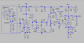
This use many tubes: 3 x 6H1P/6N1P and 1 x 6H2P/6N2P per channel!This is my take on a tube based RIAA phono stage for MM.
What's sound? You've experimented yet?
However the parts are easy looking for. Many thanks.
.
Last edited:
That's the exact opposite of the advice you'll read in all the popular books on the subject. Everybody advises to get as much low noise gain as possible from the first stage, so that successive stages don't amplify noise along with signal. I'm not saying what you're suggesting won't work, though.
I simulated the circuit and I got a final gain of 39dB. That's 5dB or so less than I shoot for, but it's definitely enough for most everybody. About 5dB more than the dual 6DJ8 RIAA designs, which is a good thing if you don't use a line stage with gain in your system.
The other thing I see in the simulation is that THD might be on the high side, even though gain is on the low side. SPICE doesn't do a perfect job of modeling THD, so a grain of salt may be necessary here...
I'll admit I've never read a book on the subject... But if the high gain tube has more noise, the position makes a difference I think. I could be wrong.
It seems ~40 db is about right for most on my purposes 🙂
RE: THD. No idea what the numbers are in SPICE, but it "sounds" good 😀
Noise floor is far below surface noise anyway.
I figure anything under 1% is pretty good compared to the average MM tracking errors and poor set up found in typical installations though 🙂
Last edited:
This use many tubes: 3 x 6H1P/6N1P and 1 x 6H2P/6N2P per channel!
What's sound? You've experimented yet?
However the parts are easy looking for. Many thanks.
.
Yes, it's a lot, but it makes the chassis cooler because there are no plate resistors inside. And it's more linear. You could use resistors instead of four of the tubes though. Higher THD etc but cheaper.
The gain stages in the Broskie Aikido and the kodabmx circuit are what Merlinb calls a 'half-mu stage'. It's basically an SRPP with the output taken from the bottom triode's plate instead of the top triode's cathode. When wired up this way, the composite 'totem-pole' stage will give half the mu of the triode used.
For example, take a 6N1P and let's wire up the two triodes in the bottle into this half-mu stage.
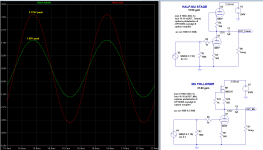
Then let's take that same 6N1P, but this time, instead of putting another 6N1P in the plate as the active load let's put a depletion-mode MOSFET there. That becomes a hybrid (tube/transistor) mu-follower stage. We'll bias this stage the same as the half-mu, and let's compare. (see attached screenshot)
Both the half-mu and mu-follower are set to
B+ = 250V
Vp = 125V (129V for the mu-follower)
Vk = 1.43V for the mu-follower, 1.5V for the half-mu
Ip = 2.69mA for the mu-follower, 2.56mA for the half-mu
I've attached a simulation of the above. You can see that:
- The Mu Follower attains almost all the 6N1P's available mu as gain. With the operating points chosen, the 6N1P mu-follower gives 37.8X gain (38X).
- The Half-Mu Stage attains just about half-- the-- mu; just about exactly 20X gain.
The THD is about the same for both at 0.065%.
Of course that THD is at 3.8V out for the mu-follower, while it's only 2V out for the half-mu.
So, if the figure of merit is most gain for least THD, the mu-follower looks like a better circuit.
If the figure of merit is lowest input capacitance, then the half-mu looks better, because the lower gain means less Miller effect on the input capacitance (which could be very important for use as the input stage of a phono preamp meant to be used with moving-magnet cartridges, which nowadays require less than 250pF total input capacitance, including cables and everything.
--
For example, take a 6N1P and let's wire up the two triodes in the bottle into this half-mu stage.
Then let's take that same 6N1P, but this time, instead of putting another 6N1P in the plate as the active load let's put a depletion-mode MOSFET there. That becomes a hybrid (tube/transistor) mu-follower stage. We'll bias this stage the same as the half-mu, and let's compare. (see attached screenshot)
Both the half-mu and mu-follower are set to
B+ = 250V
Vp = 125V (129V for the mu-follower)
Vk = 1.43V for the mu-follower, 1.5V for the half-mu
Ip = 2.69mA for the mu-follower, 2.56mA for the half-mu
I've attached a simulation of the above. You can see that:
- The Mu Follower attains almost all the 6N1P's available mu as gain. With the operating points chosen, the 6N1P mu-follower gives 37.8X gain (38X).
- The Half-Mu Stage attains just about half-- the-- mu; just about exactly 20X gain.
The THD is about the same for both at 0.065%.
Of course that THD is at 3.8V out for the mu-follower, while it's only 2V out for the half-mu.
So, if the figure of merit is most gain for least THD, the mu-follower looks like a better circuit.
If the figure of merit is lowest input capacitance, then the half-mu looks better, because the lower gain means less Miller effect on the input capacitance (which could be very important for use as the input stage of a phono preamp meant to be used with moving-magnet cartridges, which nowadays require less than 250pF total input capacitance, including cables and everything.
--
Attachments
Last edited:
Now let's compare the half-mu stage to a plain old common cathode stage with bypassed Rk.
Again I set both of them up for Vp at about 125V and Ip at about 2.5mA.
The common cathode stage has a 51k ohm plate load resistor (Rp) and the same 560 ohm cathode resistor (Rk), but now Rk is bypassed by a 200uF capacitor, so that there is no cathode degeneration.
This time, the common cathode has gain = 32X compared to the 20X gain of the half-mu stage.
THD from the common cathode stage is a whopping 0.167% at this level.
THD from the half-mu is 0.065%.
It does look like the bypassed common cathode gives more distortion.
What happens if we remove the cathode bypass capacitor and run the common cathode stage that way? This time we get 23X gain from the unbypassed common cathode stage. That's very close to the 20X gain from the half-mu.
For THD, we get 0.087% from the unbypassed common cathode stage, compared to 0.065% from the half-mu.
Which is better? I guess I don't know. Everything is a compromise between this and that.
How about running that sim using 240R instead of 560R? Does the higher current lower the THD?
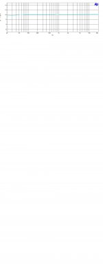
In the Junior phono amp the pcb board has a matrix for filaments so it is possible to use different tubes for gain stage and CF.
I tested many different types as:
12AX7, AT7, 5965, 7062, 12BZ7, 6922, 5751,6201 as gain stage
6922,6N6, 6H30, 12BH7, ECC99, 12AU7, 6189,5814A as CF
The smart thing is if you fix the right CF point it is possible to change the gain stage without any changes on Riaa frequency response. Just a trim or Anode on first stage.
In additiion, removing the cathode cap on each gain stage it is possible to change the total gain of 3 and 6 dB without any changes on freq. response.
In attach some tests
Walter
Attachments
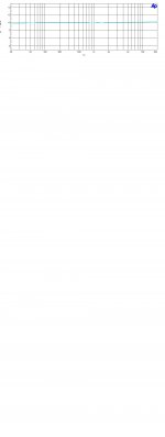
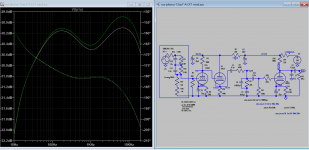
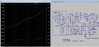
This sim is potential sch ready for build for myself soon, for sharing. A cathode follower is inserted after the Riaa Eq as buffer stage with no gain so the response is least affected, as well as applying cathode degeneration in 1st and last gain stage. THD is lower @0.017% @1mV in, 1V out (compared to 0.08% before mod).
Attachments
Last edited:
I can't understand the circuit.
You are using a CF after the riaa stage ( high impedance) then the common cathode stage with an high Zout and local degeneration
Leaving the gain only at the first stage?
And the 83 works with 0,3 mA?
Have you checked the loss on insertion of that riaa network at 1 kHz?
Until you are using the simulation you can't understand the real circuit.
Walter
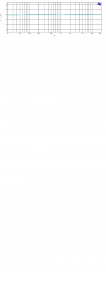
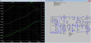
Part of the sch is from Rongong, I think you compliant to him as well, I hope i didn't step on someone toes.
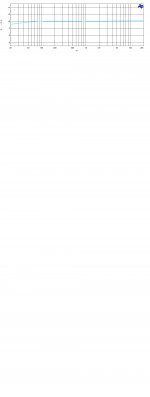
All I checked against that the sch of original RCA RIAA, esp. the critical timing component don't changed. Insert loss one end of EQ to the other end can not differ
Insert loss.
Attachments
Last edited:
Oh wow! I'm criticizing my own circuit! Well, I've learned something since I posted that a couple of years ago...
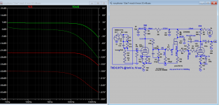
After building a similar 12AX7 phono preamp with a passively filtered power supply (no regulation), I found that the first stage 12AX7 is -extremely- sensitive to power supply impedance down around 1Hz (yes, one cycle per second). I was using something like 4.7k ohms and 33uF, which theoretically should be low enough, but there were weird rumbles happening down low from subsonic oscillations ("motorboating"). I wrote about it on this forum, and one kind person pointed out that the decoupling (dropping) resistor feeding the B+ to the first stage in a phono preamp needs to be relatively large in order to avoid these oscillations. He recommended at least 15% of the value of the first stage triode's plate load resistor. 15% of 150k is 22.5k, so there you go. I found that I needed 43k in the particular circuit I ended up building, since a 33uF electrolytic cap was already in the PCB (and it fit snugly too). Upping the decoupling resistor to 43k cured the motorboating.
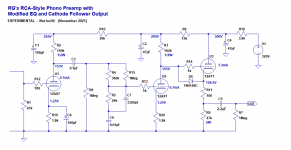
If you like that first circuit, here's an updated version that fixes those problems. I modeled it with a +320VDC B+ supply with 100mV of ripple riding on it. The output waveform shows no trace of ripple, so the power supply decoupling shown should work to filter out ripple and have low enough impedance not to oscillate at subsonic frequencies. For what it's worth, it's attached (the schematic on the left).
I'm also including a schematic of the RIAA preamp I'm listening to now. It's nothing special but I think it would be a good novice build, because it uses a passive power supply and tubes you can buy at Guitar Center. It was designed around 12AX7s, but I found that the roughly 200pF input capacitance is too much for my Audio Technica AT-VM95E cartridge, which has a recommended loading of not more than 250pF total (200pF 12AX7 Cin + 110pF tonearm cable + 30pF internal tonearm wiring = 340pF). So I put in a 12AT7 and I'll live with the reduced gain. The highs definitely sound more relaxed now, so I'm happy enough to listen to it. I am working on something better, though...
I forgot to mention that my current RIAA preamp was built using a pair of Merlinb's Compact Phono PCBs. Merlin's PCBs are good -- they're well thought out, they're well made, and they're not expensive. If you can scrounge up some 12AY7 or 6072, that would make a nice phono stage if you don't need gain of > 40dB. 12AY7 was often used in microphone preamps, so was designed for low noise. It also features much lower input C than 12AX7, so will play nicer with moving magnet cartridges. Or use a 12AT7 like I ended up doing. It distorts more, and doesn't have quite as low input C, but it can be made to work pretty well. The MOSFET source follower output frees you from worries about loading by cable runs or low impedance amplifier inputs.
The Valve Wizard
--
Which one can replace Diode 1N4148C?
- Home
- Amplifiers
- Tubes / Valves
- Build Phono Preamp